
Page 288 - Handbook of Civil Engineering Calculations, Second Edition
P. 288
PRESTRESSED CONCRETE 2.73
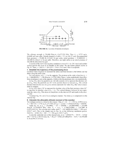
FIGURE 44. Location of tendons at midspan.
The ultimate strength is 236,000 lb/sq.in. (1,627,220 kPa). Then A s 0.723 sq.in.
2
(4.6648 cm ) per cable. Outside diameter of cable 1 /8 in. (41.27 mm). Recommended
5
final prestress 93,000 lb (413,664 N) per cable; initial prestress 93,000/0.85
109,400 lb (486,611.2 N) per cable. Therefore, use eight cables at an initial prestress of
105,500 lb (469,264.0 N) each.
1
A section of the ACI Code requires a minimum cover of 1 /2 in. (38.1 mm) and another
section permits the ducts to be bundled at the center. Try the tendon pattern shown in
Fig. 44. Thus, y [6(2.5) 2(4.5)]/8 3.0 in. (76.2 mm). This is acceptable.
7. Establish the trajectory of the prestressing force
Construct stress diagrams to represent the initial and final stresses in the bottom and top
fibers along the entire span.
For convenience, set e 0 at the supports. The prestress at the ends is therefore f bp
f tp 844,000/856 986 lb/sq.in. ( 6798.5 kPa). Since e varies parabolically from maxi-
mum at midspan to zero at the supports, it follows that the prestresses also vary parabolically.
In Fig. 45a, draw the parabolic arc AB with summit at B to represent the absolute val-
ue of f bp . Draw the parabolic arc OC in the position shown to represent f bw . The vertical
distance between the arcs at a given section represents the value of f bi ; this value is maxi-
mum at midspan.
In Fig. 45b, draw A
B
to represent the absolute value of the final prestress; draw OC
to represent the absolute value of f bw f bs . The vertical distance between the arcs repre-
sents the value of f bf . This stress is compressive in the interval ON and tensile in the inter-
val NM.
Construct Fig. 45c and d in an analogous manner. The stress f ti is compressive in the
interval OQ.
8. Calculate the allowable ultimate moment of the member
The midspan section is critical in this respect. Thus, d 62 3 59.0 in. (1498.6 mm);
2
A s 8(0.723) 5.784 sq.in. (37.3184 cm ); p A s /(bd) 5.784/[32(59.0)] 0.00306.
Apply Eq. 61, or f su 236,000(1 0.5 0.00306 236,000/5000) 219,000
lb/sq.in. (1,510,005.0 kPa). Also, T u A s f su 5.784(219,000) 1,267,000 lb
(5,635,616.0 N). The concrete area under stress 1,267,000/[0.85(5,000)] 298 sq.in.
2
(1922.7 cm ). This is the shaded area in Fig. 46, as the following calculation proves:
2
32(9.53) 4.59(1.53) 305 7 298 sq.in. (1922.7 cm ).
Locate the centroidal axis of the stressed area, or m [305(4.77) 7(9.53 0.51)]/
298 4.67 in. (118.618 mm); M u T u jd 0.90(1,267,000)(59.0 4.67) 61,950,000
in.·lb (6,999,111.0 N·m).