
Page 286 - Handbook of Civil Engineering Calculations, Second Edition
P. 286
PRESTRESSED CONCRETE 2.71
2
17,000)/[0.85(11.09)(40,000)] 0.184 sq.in./ft (3.8949 cm /m). This is the area required
at the ends.
Calculate the minimum web-reinforcement area by applying
f s
s
A s
A v (65)
80 f y (b
d) 0.5
or A v (1.089/80)(248,000/40,000)12/(12.74 11.09) 0.5 0.085 sq.in./ft (1.7993
2
cm /m).
9. Calculate the camber under full dead load
6
6
From the previous procedure, E c ( /3)(3.644)(10) 1.215 10 lb/sq.in. (8.377 10 6
1
6
2
6
9
kPa); E c I 1.215(10) (7240) 8.8 10 lb·sq.in. (25.25 10 N·m ); ADL 5(401)
9
4
(40) (1728)/[384(8.8)(10) ] 2.62 in. ( 66.548 mm). By Eq. 58, p 0.85(181,400)
9
2
(6.07)(40) (144)/[8(8.8)(10) ] 3.06 in. (77.724 mm); 3.06 2.62 0.44 in.
(11.176 mm).
DESIGN OF A POSTTENSIONED GIRDER
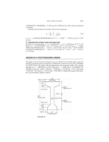
The girder in Fig. 42 has been selected for use on a 90-ft (27.4-m) simple span to carry the
following superimposed loads: dead load, 1160 lb/lin ft (16,928.9 N/m); live load, 1000 lb/lin
ft (14,593.9 N/m). The girder will be posttensioned with Freyssinet cables. The concrete
strengths are f c
5000 lb/sq.in. (34,475 kPa) and f ci
4000 lb/sq.in. (27,580 kPa). The
allowable stresses are: initial, 2400 and 190 lb/sq.in. ( 16,548 and 1310.1 kPa); final,
2250 and 425 lb/sq.in. ( 15,513.8 and 2930.4 kPa). Complete the design of this mem-
ber, and calculate the camber at transfer.
FIGURE 42