
Page 283 - Handbook of Civil Engineering Calculations, Second Edition
P. 283
2.68 REINFORCED AND PRESTRESSED CONCRETE ENGINEERING AND DESIGN
DESIGN OF A DOUBLE-T ROOF BEAM
The beam in Fig. 39 was selected for use on a simple span of 40 ft (12.2 m) to carry the
2
2
following loads: roofing, 12 lb/sq.ft.(574.5 N/m ); snow, 40 lb/sq.ft.(1915.1 N/m ); total,
2
52 lb/sq.ft.(2489.6 N/m ). The member will be pretensioned with straight seven-wire
2
strands, /16 in. (11.11 mm) diameter, having an area of 0.1089 sq.in. (0.70262 cm ) each
7
and an ultimate strength of 248,000 lb/sq.in. (1,709,960.0 kPa). The concrete strengths
are f c
5000 lb/sq.in. (34,475.0 kPa) and f ci
4000 lb/sq.in. (27,580.0 kPa). The allow-
able stresses are: initial, 2400 and 190 lb/sq.in. ( 16,548.0 and 1310.1 kPa); final,
2250 and 425 lb/sq.in. ( 15,513.8 and 2930.4 kPa). Investigate the adequacy of
this section, and design the tendons. Compute the camber of the beam after the concrete
has hardened and all dead loads are present. For this calculation, assume that the final val-
ue of E c is one-third of that at transfer.
Calculation Procedure:
1. Compute the properties of the cross section
Let f bf and f tf denote the respective stresses at midspan and f bi and f ti denote the respective
stresses at the support. Previous calculation procedures demonstrated that where the sec-
tion moduli are excessive, the minimum prestressing force is obtained by setting f bf and f ti
equal to their allowable values.
4
4
2
Thus A 316 sq.in. (2038.8 cm ); I 7240 in (30.14 dm ); y b 10.98 in. (278.892
3
3
3
mm); y t 5.02 in. (127.508 mm); S b 659 in (10,801.0 cm ); S t 1442 in (23,614
3
cm ); w w (316/144)150 329 lb/lin ft (4801.4 N/m).
2. Calculate the total midspan moment due to gravity loads
and the corresponding stresses
Thus w s 52(6) 312 lb/lin ft (4553.3 N/m); w w , 329 lb/lin ft (4801.4 N/m); and M w
M s ( /8)(641)(40 )(12) 1,538,000 in.·lb (173,763.2 N·m); f bw f bs 1,538,000/659
2
1
2334 lb/sq.in. ( 16,092.9 kPa); f tw f ts 1,538,000/1442 1067 lb/sq.in.
( 7357.0 kPa).
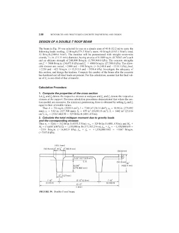
FIGURE 39. Double-T roof beam.