
Page 287 - Handbook of Civil Engineering Calculations, Second Edition
P. 287
2.72 REINFORCED AND PRESTRESSED CONCRETE ENGINEERING AND DESIGN
Calculation Procedure:
1. Compute the properties of the cross section
Since the tendons will be curved, the initial stresses at midspan may be equated to the al-
2
lowable values. The properties of the cross section are A 856 sq.in. (5522.9 cm ); I
4
4
394,800 in (1643 dm ); y b 34.6 in. (878.84 mm); y t 27.4 in. (695.96 mm); S b 11,410
3
3
3
3
in (187,010 cm ); S t 14,410 in (236,180 cm ); w w 892 lb/lin ft (13,017.8 N/m).
2. Calculate the stresses at midspan caused by gravity loads
Thus f bw 950 lb/sq.in. ( 6550.3 kPa); f bs 2300 lb/sq.in. ( 15,858.5 kPa); f tw
752 lb/sq.in. ( 5185.0 kPa); f ts 1820 lb/sq.in. ( 12,548.9 kPa).
3. Test the section adequacy
To do this, equate f bf and f ti to their allowable values and compute the corresponding val-
ues of f bi and f tf . Thus f bf 0.85 f bp 950 2300 425; f ti f tp 752 190;
therefore, f bp 3324 lb/sq.in. ( 22,919.0 kPa) and f tp 942 lb/sq.in. ( 6495.1
kPa); f bi 3324 950 2374 < 2400 lb/sq.in. (16,548.0 kPa). This is acceptable.
And f tf 0.85( 942) 752 1820 1771 < 2250 lb/sq.in. (15,513.8 kPa). This is
acceptable. The section is therefore adequate.
4. Find the minimum prestressing force and its eccentricity
at midspan
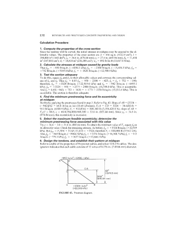
Do this by applying the prestresses found in step 3. Refer to Fig. 43. Slope of AB [3324
( 942)]/62 68.8 lb/(sq.in.·in) (18.68 kPa/mm); F i /A CD 3324 34.6(68.8)
944 lb/sq.in. (6508.9 kPa); F i 944(856) 808,100 lb (3,594,428.8 N); slope of AB
F i e/I 68.8; e 68.8(394,800)/808,100 33.6 in. (853.44 mm). Since y b 34.6 in.
(878.84 mm), this eccentricity is excessive.
5. Select the maximum feasible eccentricity; determine the
minimum prestressing force associated with this value
Try e 34.6 3.0 31.6 in. (802.64 mm). To obtain the minimum value of F i , equate f bf to
its allowable value. Check the remaining stresses. As before, f bp 3324 lb/sq.in. ( 22,919
kPa). But f bp , F i /856 31.6F i /11,410 3324; therefore F i 844,000 lb (3754.1 kN).
Also, f tp 865 lb/sq.in. ( 5964.2 kPa); f bi 2374 lb/sq.in. ( 16,368.7 kPa); f ti 113
lb/sq.in. ( 779.1 kPa); f tf 1837 lb/sq.in. ( 12,666.1 kPa).
6. Design the tendons, and establish their pattern at midspan
Refer to a table of the properties of Freyssinet cables, and select 12/0.276 cables. The des-
ignation indicates that each cable consists of 12 wires of 0.276-in. (7.0104-mm) diameter.
FIGURE 43. Prestress diagram.