
Page 292 - Handbook of Civil Engineering Calculations, Second Edition
P. 292
PRESTRESSED CONCRETE 2.77
FIGURE 48
respectively, are e a 1 in. (25.4 mm); e m 30 in. (762.0 mm); e b 3 in. ( 76.2 mm).
Evaluate the prestress shear and prestress moment at section C (a) by applying the proper-
ties of the trajectory at C; (b) by considering the prestressing action of the steel on the
concrete in the interval AC.
Calculation Procedure:
1. Compute the eccentricity and slope of the trajectory at C
Use Eqs. 66 and 67. Let m denote the slope of the trajectory. This is positive if the trajec-
tory slopes downward to the right. Thus e a 2e m e b 1 60 3 62 in. (1574.8
mm); 3e a 4e m e b , 3 120 3 120 in. ( 3048 mm); e m 2( 62)(20/100) 2
2
120(20/100) 1 20.04 in. (509.016 mm); m c 4( 62/12)(20/100 ) ( 120/12
100) 0.0587.
2. Compute the prestress shear
and moment at C
Thus V pc m c F i 0.0587(860,000)
50,480 lb ( 224,535.0 N); M pc
F i e 860,000(20.04) 17,230,000
in.·lb ( 1,946,645.4 N·m). This concludes
the solution to part a.
3. Evaluate the vertical
component w of the radial force
on the concrete in a unit
longitudinal distance
An alternative approach to this problem
is to analyze the forces that the tendons
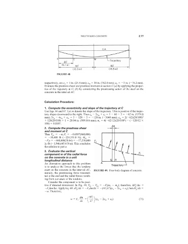
exert on the concrete in the interval AC, FIGURE 49. Free-body diagram of concrete.
namely, the prestressing force transmit-
ted at the end and the radial forces result-
ing from curvature of the tendons.
Consider the component w to be posi-
tive if directed downward. In Fig. 49, V pr V pq F i (m r m q ); therefore, V p / x
2
F i m/ x. Apply Eq. 68: dV p /dx F i dm/dx (4F i /L )(e a 2e m e b ); but dV p /dx
w. Therefore,
dm 4F i
w F i (e a 2e m e b ) (71)
dx L 2