
Page 290 - Handbook of Civil Engineering Calculations, Second Edition
P. 290
PRESTRESSED CONCRETE 2.75
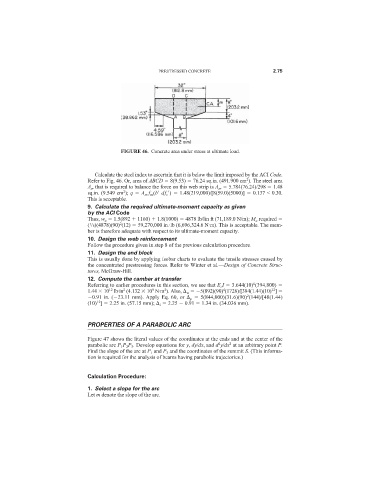
FIGURE 46. Concrete area under stress at ultimate load.
Calculate the steel index to ascertain that it is below the limit imposed by the ACI Code.
2
Refer to Fig. 46. Or, area of ABCD 8(9.53) 76.24 sq.in. (491.900 cm ). The steel area
A sr that is required to balance the force on this web strip is A sr 5.784(76.24)/298 1.48
2
sq.in. (9.549 cm ); q A sr f su (b
df c
) 1.48(219,000)/[8(59.0)(5000)] 0.137 < 0.30.
This is acceptable.
9. Calculate the required ultimate-moment capacity as given
by the ACI Code
Thus, w u 1.5(892 1160) 1.8(1000) 4878 lb/lin ft (71,189.0 N/m); M u required
2
1
( /8)(4878)(90) (12) 59,270,000 in.·lb (6,696,324.6 N·m). This is acceptable. The mem-
ber is therefore adequate with respect to its ultimate-moment capacity.
10. Design the web reinforcement
Follow the procedure given in step 8 of the previous calculation procedure.
11. Design the end block
This is usually done by applying isobar charts to evaluate the tensile stresses caused by
the concentrated prestressing forces. Refer to Winter et al.—Design of Concrete Struc-
tures, McGraw-Hill.
12. Compute the camber at transfer
6
Referring to earlier procedures in this section, we see that E c I 3.644(10) (394,800)
4
12
1.44 10 lb·in (4.132 10 N·m ). Also, w 5(892)(90) (1728)/[384(1.44)(10) ]
9
2
2
12
2
0.91 in. ( 23.11 mm). Apply Eq. 60, or p 5(844,000)(31.6)(90) (144)/[48(1.44)
12
(10) ] 2.25 in. (57.15 mm); i 2.25 0.91 1.34 in. (34.036 mm).
PROPERTIES OF A PARABOLIC ARC
Figure 47 shows the literal values of the coordinates at the ends and at the center of the
2
2
parabolic arc P 1 P 2 P 3 . Develop equations for y, dy/dx, and d y/dx at an arbitrary point P.
Find the slope of the arc at P 1 and P 3 and the coordinates of the summit S. (This informa-
tion is required for the analysis of beams having parabolic trajectories.)
Calculation Procedure:
1. Select a slope for the arc
Let m denote the slope of the arc.