
Page 281 - Handbook of Civil Engineering Calculations, Second Edition
P. 281
2.66 REINFORCED AND PRESTRESSED CONCRETE ENGINEERING AND DESIGN
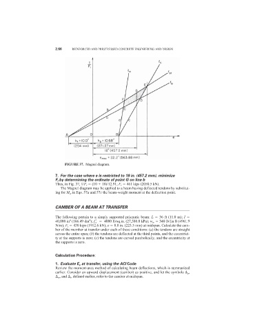
FIGURE 37. Magnel diagram.
7. For the case where e is restricted to 18 in. (457.2 mm), minimize
F i by determining the ordinate of point G on line b
Thus, in Fig. 37, 1/F i (10 18)/12.91; F i 461 kips (2050.5 kN).
The Magnel diagram may be applied to a beam having deflected tendons by substitut-
ing for M w in Eqs. 57a and 57c the beam-weight moment at the deflection point.
CAMBER OF A BEAM AT TRANSFER
The following pertain to a simply supported prismatic beam: L 36 ft (11.0 m); I
4
4
40,000 in (166.49 dm ); f ci
4000 lb/sq.in. (27,580.0 kPa); w w 340 lb/lin ft (4961.9
N/m); F i 430 kips (1912.6 kN); e 8.8 in. (223.5 mm) at midspan. Calculate the cam-
ber of the member at transfer under each of these conditions: (a) the tendons are straight
across the entire span; (b) the tendons are deflected at the third points, and the eccentrici-
ty at the supports is zero; (c) the tendons are curved parabolically, and the eccentricity at
the supports is zero.
Calculation Procedure:
1. Evaluate E c at transfer, using the ACI Code
Review the moment-area method of calculating beam deflections, which is summarized
earlier. Consider an upward displacement (camber) as positive, and let the symbols p ,
w , and i , defined earlier, refer to the camber at midspan.