
Page 279 - Handbook of Civil Engineering Calculations, Second Edition
P. 279
2.64 REINFORCED AND PRESTRESSED CONCRETE ENGINEERING AND DESIGN
investigation. Calculate f bp and f tp by expressing these
stresses as functions of the kern distances of the
section.
Calculation Procedure:
1. Consider the prestressing force to be
applied at each kern point, and evaluate
the kern distances
Let Q b and Q t denote the points at which a compres-
sive force must be applied to induce a zero stress in the
top and bottom fiber, respectively. These are referred to
as the kern points of the section, and the distances k b
and k t , from the centroidal axis to these points are
called the kern distances.
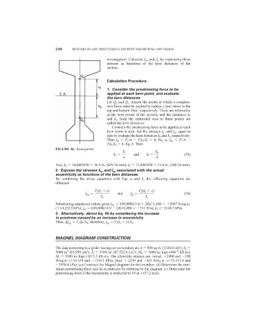
Consider the prestressing force to be applied at each
kern point in turn. Set the stresses f tp and f bp equal to
zero to evaluate the kern distances k b and k t , respectively.
Thus f tp F i /A F i k b /S t 0, Eq. a; f bp F i /A
F i k t /S b 0, Eq. b. Then
FIGURE 36. Kern points.
S t S b
k b and k t (55)
a A
And, k b 14,400/850 16.9 in. (429.26 mm); k t 11,400/850 13.4 in. (340.36 mm).
2. Express the stresses f bp and f tp associated with the actual
eccentricity as functions of the kern distances
By combining the stress equations with Eqs. a and b, the following equations are
obtained:
F i (k t e) F i (k b e)
f bp and f tp (56)
S b S t
Substituting numerical values gives f bp 630,000(13.4 24)/11,400 2067 lb/sq.in.
( 14,252.0 kPa); f tp 630,000(16.9 24)14,400 311 lb/sq.in. ( 2144.3 kPa).
3. Alternatively, derive Eq. 56 by considering the increase
in prestress caused by an increase in eccentricity
Thus, f bp F i e/S b ; therefore, f bp F i (k t e)/S b .
MAGNEL DIAGRAM CONSTRUCTION
The data pertaining to a girder having curved tendons are A 500 sq.in. (3226.0 cm ); S b
2
3
3
3
3
5000 in (81,950 cm ); S t 5340 in (87,522.6 cm ); M w 3600 in.·kips (406.7 kN·m);
M s 9500 in.·kips (1073.3 kN·m). The allowable stresses are: initial, 2400 and 190
lb/sq.in. ( 16,548 and 1310.1 kPa); final, 2250 and 425 lb/sq.in. ( 15,513.8 and
2930.4 kPa). (a) Construct the Magnel diagram for this member. (b) Determine the min-
imum prestressing force and its eccentricity by referring to the diagram. (c) Determine the
prestressing force if the eccentricity is restricted to 18 in. (457.2 mm).