
Page 298 - Handbook of Civil Engineering Calculations, Second Edition
P. 298
PRESTRESSED CONCRETE 2.83
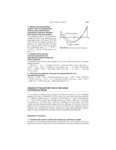
2. Replace the prestressing
system with two hypothetical
systems that jointly induce
eccentricity moments identical
with those of the true system
This constitutes method 2. For this purpose,
consider the beam to be subjected to two
prestressing forces of 96 kips (427.0 kN)
each. One has the parabolic trajectory de-
scribed in the earlier procedure; the other
has a trajectory that is linear in each span,
the eccentricities being e a 0.72 FIGURE 54. Prestress-moment diagrams.
( 0.40) 0.32 in. ( 8.128 mm), e b 0,
and e c 0.
3. Evaluate the prestress
moments induced by the
hypothetical system having the
linear trajectory
The tendons exert a force on the concrete at A, B, and C, but only the force at A causes
bending moment.
Thus, M pa F i e a 96,000( 0.32)/12 2560 ft·lb (3471.4 N·m). Also, M pa L 1
2M pb (L 1 L 2 ) M pc L 2 0. But M pc 0; therefore, M pb 512 ft·lb ( 694.3 N·m);
M pd /2(2560 512) 1024 ft·lb (1388.5 N·m); M pe /2( 512) 256 ft·lb
1
1
( 347.1 N·m).
4. Find the true prestress moments by superposing the two
hypothetical systems
Thus M pa 3200 2560 5760 ft·lb (7810.6 N·m); M pd 4704 1024 3680 ft·lb
( 4990.1 N·m); M pb 9792 512 9280 ft·lb (12,583.7 N·m); M pe 5024 256
5280 ft·lb ( 7159.7 N·m); M pc 4800 ft·lb (6508.8 N·m).
DESIGN OF TRAJECTORY FOR A TWO-SPAN
CONTINUOUS BEAM
A T beam that is continuous across two spans of 120 ft (36.6 m) each is to carry a uniformly
distributed live load of 880 lb/lin ft (12,842.6 N/m). The cross section has these properties:
4
4
2
A 1440 sq.in. (9290.8 cm ); I 752,000 in (3130.05 dm ); y b 50.6 in. (1285.24 mm);
y t 23.4 in. (594.36 mm). The allowable stresses are: initial, 2400 and 60 lb/sq.in.
( 16,548.0 and 413.7 kPa); final, 2250 and 60 lb/sq.in. ( 15,513.8 and 413.7 kPa).
Assume that the minimum possible distance from the extremity of the section to the cen-
troidal axis of the prestressing steel is 9 in. (228.6 mm). Determine the magnitude of the pre-
stressing force, and design the parabolic trajectory (a) using solely prestressed reinforce-
ment; (b) using a combination of prestressed and non-prestressed reinforcement.
Calculation Procedure:
1. Compute the section moduli, kern distances, and beam weight
For part a, an exact design method consists of these steps: First, write equations for the pre-
stress moment, beam-weight moment, maximum and minimum potential superimposed-load