
Page 300 - Handbook of Civil Engineering Calculations, Second Edition
P. 300
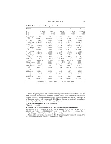
PRESTRESSED CONCRETE                  2.85

                              TABLE 4. Calculations for Two-Span Beam: Part a
                              Section        1          2           3         4          B
                                             0.0675      0.0950     0.0825     0.0300     0.0625
                              1 C 1
                                             0.0125      0.0250     0.0375     0.0500     0.0625
                              2 C 2
                                             0.0550      0.0700     0.0450     0.0200     0.1250
                              3 C 3
                              4 f bw , lb/sq.in.   959   1,221    785        349       2,180
                                (kPa)    ( 6,611)   ( 8,418)    ( 5,412)   ( 2406)  ( 15,029)
                              5 f bs1 , lb/   691      972        844        307        640
                                sq.in. (kPa)  ( 4,764)  ( 6,701)   5,819)  ( 2,116)  ( 4,412)
                              6 f bs2 , lb/   128      256        384        512        640
                                sq.in. (kPa)  ( 882)  ( 1,765)  ( 2,647)  ( 3,530)   ( 4,412)
                              7 f tw , lb/sq.in.   444   565      363        161       1,008
                                (kPa)    ( 3,060)    ( 3895)    ( 2,503)  ( 1,110)   ( 6,949)
                              8 f ts1 , lb/sq.in.   319   450     390        142        296
                                (kPa)    ( 2,199)   ( 3,102)    ( 2689)    ( 979)    ( 2,041)
                              9 f ts2 , lb/sq.in.   59   118      177        237        296
                                (kPa)     ( 407)      ( 813)    ( 1,220)  ( 1,634)   ( 2,041)
                              10 e con , in.   17.19    21.87      14.06       6.25      39.05
                                (mm)      ( 436.6)    ( 555.5)   ( 357.1)  ( 158.8)   ( 991.9)
                              11 f bp , lb/sq.in.   2,148   2,513     1,903   318      2,243
                                (kPa)   ( 14,808)   ( 17,325)  ( 13,119)  ( 2,192)  ( 15,463)
                              12 f tp , lb/sq.in.   185   16      298       1,031      2,215
                                (kPa)     ( 128)      ( 110)    ( 2,054)  ( 7,108)  ( 15,270)
                                0.85f bp
                              13 lb/sq.in.   1,826    2,136      1,618       270       1,906
                                (kPa)   ( 12,588)   ( 14,726)  ( 11,154)  ( 1,861)  ( 13,140)
                                0.85f tp
                              14 lb/sq.in.   157        14        253        876       1,883
                                (kPa)    ( 1,082)     ( 97)     ( 1,744)  ( 6,039)  ( 12,981)
                                          At midspan: C 3   0.0625 and e con   19.53 in. (496.1 mm)


                                Since the gravity loads induce the maximum positive moment at section 2 and the
                              maximum negative moment at section B, the prestressing force and its trajectory will be
                              designed to satisfy the stress requirements at these two sections. (However, the stresses at
                              all boundary sections will be checked.) The Magnel diagram for section 2 is similar to
                              that in Fig. 37, but that for section B is much different.
                              3. Compute the value of C 3 at midspan
                              Thus, C 3   0.0625.
                              4. Apply the moment coefficients to find the gravity-load stresses
                                                                         2
                              Record the results in Table 4. Thus M w   C 3 (1500)(120) (12)   259,200,000C 3 in.·lb
                              (29.3C 3 kN·m); f bw   259,200,000C 3 /14,860   17,440C 3 ; f bs1   10,230C 1 ; f bs2
                               10,230C 2 ; f tw   8065C 3 ; f ts1   4731C 1 ; f ts2   4731C 2 .
                                Since S t far exceeds S b , it is manifest that the prestressing force must be designed to
                              confine the bottom-fiber stresses to the allowable range.