Page 248 - Handbook of Electrical Engineering
P. 248

232    HANDBOOK OF ELECTRICAL ENGINEERING

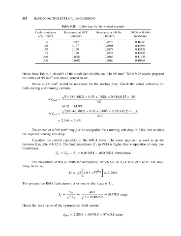
                                      Table 9.28. Cable data for the worked example
                                                   ◦
                      Cable conductor  Resistance at 90 C  Reactance at 60 Hz  0.033r + 0.944x
                               2
                        area (mm )        (ohm/km)            (ohm/km)          (ohm/km)
                            95              0.247              0.0872            0.16383
                           120              0.197              0.0868            0.14694
                           150              0.160              0.0874            0.13531
                           185              0.128              0.0876            0.12493
                           240              0.0989             0.0866            0.11439
                           300              0.0802             0.0860            0.10765


                                                                          2
              Hence from Tables 9.16 and 9.17 the small size of cable could be 95 mm . Table 9.28 can be prepared
                               2
              for cables of 95 mm and above, routed in air.
                                   2
                    Hence a 300 mm would be necessary for the starting duty. Check the actual volt-drop for
              both starting and running currents.
                                      √
                                       31408(0.0802 × 0.33 + 0.086 × 0.944)0.25 × 100
                              V start =
                                                          440
                                   = 14.92 = 14.9%
                                      √
                                       3245.4(0.0802 × 0.92 + 0.086 × 0.3919)0.25 × 100
                               V run =
                                                           440
                                   = 2.596 = 2.6%

                                        2
                    The choice of a 300 mm may just be acceptable for a running volt-drop of 2.6%, but satisfies
              the required starting volt-drop.
                    Calculate the cut-off capability of the 400 A fuses. The same approach is used as in the
              previous Example 9.4.3.5.1. The fault impedance Z f in (9.8) is higher due to operation of only one
              transformer,
                                  Z f = Z bs + Z t = 0.001054 + j0.006821 ohms/phase

                    The magnitude of this is 0.006902 ohms/phase, which has an X/R ratio of 6.4715. The dou-
              bling factor is,

                                              √           −π
                                          D =   2 1.0 + e 6.4715 = 2.2846

              The prospective RMS fault current at or near to the fuses is I f ,

                                                      460
                                          V os
                                    I f = √    = √             = 38478.9 amps
                                          3Z f     3 × 0.006902
              Hence the peak value of the symmetrical fault current


                                      I fpka = 2.2846 × 38478.9 = 87908.8 amps
   243   244   245   246   247   248   249   250   251   252   253