
Page 249 - Handbook of Electrical Engineering
P. 249
CABLES, WIRES AND CABLE INSTALLATION PRACTICES 233
Again let the cut-off current be 20% of I fpka ,
I co 0.2 × 87909 = 17582 amps
And
87909
I fpka
I frms = √ = √ = 31080 amps
2 2 2 2
From Figure 9.5 it can be seen that a 400 amp fuse will cut-off, with a higher cut-off current
than 17,582 amps but still within a good margin at 30,000 amps, i.e. a factor of 34% instead of 20%.
2
The I-squared-t characteristic of a 300 mm XLPE cable can be found from,
√ 143 × 300 42900
t = =
I I
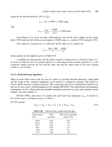
Several points on the graph are given in Table 9.29.
A suitable fuse characteristic and the cable I-squared-t characteristic are plotted in Figure 9.7.
It can be seen that the fuse will operate rapidly for a wide range of fault currents, that there is a wide
I-squared-t margin between the fuse and the cable, and that the corner point of the motor starting
current is well avoided.
9.4.3.6 Earth fault loop impedance
When an earth fault occurs at the far end of a cable it is possible that the armouring, cable gland
and the frame of the consumer equipment can be raised to a dangerous potential with respect to
electric shock exposure to human operators. This subject has been given considerable attention over
the last 20 years, and is well documented in for example IEC60364. The international documentation
concentrates on low voltage fixed and portable equipment protected by fuses and miniature circuit
breakers. See also Chapter 13.
BS7430 (1998), sub-section 3.13, defines the earth fault loop impedance Z loop in relation to
the various types of earthing systems, as follows.
For TN systems:
(9.9)
Z loop = Z nez + Z sec + Z c + Z a + Z bond + Z mr
Table 9.29. Cable and fuse currents and time data
Cable current Time 400 A fuse operating
(kA) (seconds) current (kA)
429.0 0.01 11.0
191.8 0.05 9.0
135.7 0.10 7.5
60.7 0.50 5.3
42.9 1.00 4.3
19.2 5.00 3.0