
Page 255 - Handbook of Electrical Engineering
P. 255
CABLES, WIRES AND CABLE INSTALLATION PRACTICES 239
√
365.82(0.2960 × 0.85 + 0.0268 × 0.5268)100
V run =
415
= 7.299%.
From (9.3) for ‘starting’ conditions,
cos Ø = 0.45 and sin Ø = 0.8930
√
3460.74(0.2960 × 0.45 + 0.0268 × 0.8930)100
V start =
415
= 30.216%.
Table 9.33 shows the volt-drop results for all the available cables.
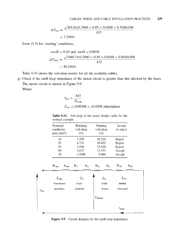
g) Check if the earth loop impedance of the motor circuit is greater than that allowed by the fuses.
The motor circuit is shown in Figure 9.9.
Where
415
V ph =
Z loopc
Z sec = 0.00308 + j0.0308 ohms/phase
Table 9.33. Volt-drop in the motor feeder cable for the
worked example
Nominal Running Starting Accept
conductor volt-drop volt-drop or reject
2
area (mm ) (%) (%)
16 7.299 30.216 Reject
25 4.733 20.492 Reject
35 3.498 15.820 Reject
50 2.672 12.792 Accept
70 1.9306 9.800 Accept
Figure 9.9 Circuit diagram for the earth loop impedance.