
Page 415 - Handbook of Electrical Engineering
P. 415
404 HANDBOOK OF ELECTRICAL ENGINEERING
A time delay is incurred until the zero is reached, and the corresponding angle is ‘α’ which is called
◦
the ‘delay angle’. This angle occurs from zero to 30 , and the type of operation is called ‘Mode 2’.
If the load current is further increased a new condition arises, called ‘Mode 3’ operation.
The decaying current requires more time to reach zero. During this extra time there is a short-term
three-phase short circuit and the output voltage is discontinuous at zero for this period. The output
voltage appears as a train of saw-toothed pulses. The average value of this voltage is capable of
driving more current into the load. As this occurs the delay or ‘retardation angle γ ’ increases until
◦
it eventually reaches 60 , at which angle there is a complete three-phase short circuit and the output
voltage is zero. During the increase in retardation angle the AC phase currents change their shape
from a quazi-trapezium to a pure fundamental sine wave. The AC current is then limited only by the
impedance of the transformer and any impedance upstream.
References 7 and 8 describes these commutation process in relation to the use of diode bridges
in the main rotor circuits of synchronous generators.
15.2.1.2 Harmonic components
The waveform of the current in the secondary winding, phase AS of Figure 15.1 is shown in
◦
Figure 15.2 in relation to its phase voltage. The operating condition is for angle u = 10 in Mode 1,
◦
when the delay angles α has a nominal value 15 .
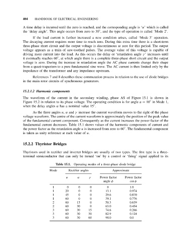
As the three angles u, α and γ increase the current waveform moves to the right of the phase
voltage waveform. The centre of the current waveform is approximately the position of the peak value
of the fundamental current component. Consequently as the current increases the power factor of the
fundamental current decreases. Table 15.1 shows values of the harmonic components of current and
◦
the power factor as the retardation angle u is increased from zero to 60 . The fundamental component
is taken as unity reference at each value of u.
15.2.2 Thyristor Bridges
Thyristors used in rectifier and inverter bridges are usually of two types. The first type is a three-
terminal semiconductor that can only be turned ‘on’ by a control or ‘firing’ signal applied to its
Table 15.1. Operating modes of a three-phase diode bridge
Mode Rectifier angles Approximate
u α γ Power factor Power factor
angle φ cos φ
1 0 0 0 0 1.0
1 20 0 0 13.1 0.974
1 45 0 0 29.6 0.870
1 60 0 0 39.1 0.776
2 60 15 0 50.3 0.639
2 60 30 0 63.0 0.454
3 60 30 15 74.6 0.266
3 60 30 30 82.9 0.124
3 60 30 60 90.0 0.0