
Page 414 - Handbook of Electrical Engineering
P. 414
HARMONIC VOLTAGES AND CURRENTS 403
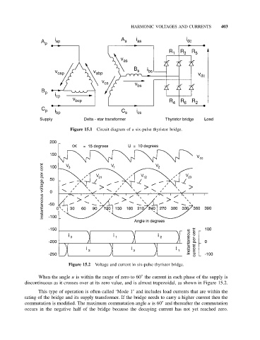
Figure 15.1 Circuit diagram of a six-pulse thyristor bridge.
Figure 15.2 Voltage and current in six-pulse thyristor bridge.
◦
When the angle u is within the range of zero to 60 the current in each phase of the supply is
discontinuous as it crosses over at its zero value, and is almost trapezoidal, as shown in Figure 15.2.
This type of operation is often called ‘Mode 1’ and includes load currents that are within the
rating of the bridge and its supply transformer. If the bridge needs to carry a higher current then the
◦
commutation is modified. The maximum commutation angle u is 60 and thereafter the commutation
occurs in the negative half of the bridge because the decaying current has not yet reached zero.