
Page 409 - Handbook of Electrical Engineering
P. 409
398 HANDBOOK OF ELECTRICAL ENGINEERING
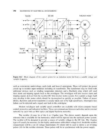
Figure 14.5 Block diagram of the control system for an induction motor fed from a variable voltage and
variable frequency.
such as overcurrent, undervoltage, earth fault, and fuses if appropriate. These will protect the power
circuit up to rectifier input terminals including its transformer. The transformer may be fitted with
additional devices such as winding temperature detectors and a Buchholz relay which will send
their alarm and tripping signals back to the switchgear. The switchgear will also receive alarm and
tripping signals derived from the rectifier-DC link-inverter motor system. For example a major fault
may develop in the motor which should be de-energised as quickly as possible. Failure of power
diodes, thyristors and power transistors is usually taken care of by high speed fuses, whereupon fuse
failure can be detected and a signal sent back to the switchgear.
Modern switchgear and variable speed controllers are available with micro-computer based
control, protective and indication facilities. These can communicate between each other and to external
networks by such links as fibre optics and digital hardwire networks.
The rectifier (1) may be of the 6 or 12-pulse type. The choice mainly depends upon the
tolerance that is available for the harmonics, which will be injected into the upstream power system.
The rectifier will be designed to provide a source of variable voltage to the DC link. The 12-pulse
type will usually be necessary for the highly rated motors within their voltage level. Inside the rectifier
compartment will be a set of voltage transformers (9) which will be used to derive a set of firing
pulses (10) for the rectifier elements. These pulses will be in synchronism with the power supply.