
Page 404 - Handbook of Electrical Engineering
P. 404
VARIABLE SPEED ELECTRICAL DRIVERS 393
Figure 14.3 Schematic diagram of a variable voltage and variable frequency rectifier inverter system for an
induction motor.
for accurate speed control and other signals for protection purposes, e.g. short circuit, and stalling,
current limiting.
If an induction motor is run at a frequency below its normal operating frequency, the air-
gap flux will rise if the supply voltage magnitude is kept constant. The rise in flux will cause
magnetic saturation in the iron circuit of the motor and this in turn will cause a very large increase
in magnetising current in the X m branch shown in Figures 5.1 or 15.11.
The applied voltage must be reduced almost in proportion to the frequency so that the flux
remains almost constant. The control of the flux is achieved by using a frequency sensing circuit to
fire the rectifier thyristors. As the frequency is reduced the X-to-R ratio of the complete circuit is
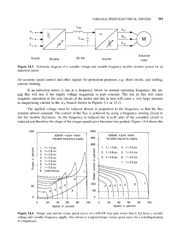
reduced and therefore the shape of the torque-speed curve becomes less peaked. Figure 14.4 shows the
Figure 14.4 Torque and current versus speed curves of a 630 kW four-pole motor that is fed from a variable
voltage and variable frequency supply. Also shown is a typical torque versus speed curve for a centrifugal pump
or compressor.