Page 495 - Handbook of Electrical Engineering
P. 495

GENERALISED THEORY OF ELECTRICAL MACHINES      485

              For a squirrel cage induction motor none of the mutual and self-inductances are functions of the
              rotor position.
                   Equation (20.2) can be applied to v a , v b and v c and again to i a , i b and i c . The zero sequence
              terms can be neglected.
                   The substitution exercise is very tedious, but eventually yields the following expression:-

                                                                          
                             v d          i d       p    +ω    0  0   0     ψ d
                                                   −ω
                           v q          i q             p    0  0   0   ψ q  
                                       
                                                                          
                                       
                             v f  =  R    i f                              ψ f
                                             +    0    0    p  0   0              (20.5)
                                                                          
                                       
                            v kd           i kd                              ψ kd
                                                 0     0    0  p   0      
                                                      0     0    0  0   p
                            v kq           i kq                              ψ kq
                                             T
              Where, [R] = [R a ,R a ,R f ,R kd ,R kq ] and superscript T means transpose.
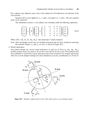
              Note: Since the damper circuits have no external connections and are short circuited by end rings,
                   the terminal voltages v kd and v kq are zero, as shown in Figure 20.2.
           c) Mutual inductances
              Most authors identity the various mutual inductances in each axis of (20.4) e.g. M ab , M af , M akd ,
              and then assume them to be equal as, M d for the d-axis and M q for the q-axis. Some analyses have
              been published in which these mutual inductances have been assumed to be unequal, particularly
              when two or more damper windings have been included in each axis, see References 6, 15 and 16.


                  Figure 20.2  Mutually coupled circuits in the A-B-C phase and d-q axis reference frames.
   490   491   492   493   494   495   496   497   498   499   500