
Page 498 - Handbook of Electrical Engineering
P. 498
488 HANDBOOK OF ELECTRICAL ENGINEERING
If i f and i kd are eliminated in (20.12) and (20.14) and (20.6) and after much manipulation
the following reactances and time constants can be determined. References 3, 5 and 17 describe
the elimination process and the necessary assumptions required to obtain the time constants.
By referring to Chapter VI of Reference 3 sub-section 25, in particular, the algebraic sub-
stitutions and a sequence of approximations can be studied, from which the following results
are most frequently used. In sub-section 20.2c herein the symbols for the leakage reactances
are usually quoted slightly differently, X la , X lkd , X klq and X lfd become X a , X kd , X kq and X f
respectively. It should be remembered that these are leakage reactances, wherein the suffix ‘1’
emphasises the fact.
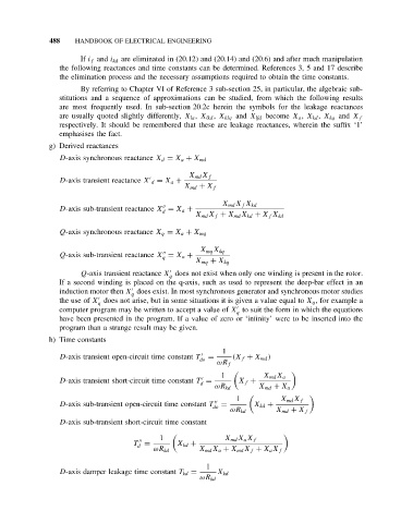
g) Derived reactances
D-axis synchronous reactance X d = X a + X md
X md X f
D-axis transient reactance X d = X a +
X md + X f
X md X f X kd
D-axis sub-transient reactance X = X a +
d
X md X f + X md X kd + X f X kd
Q-axis synchronous reactance X q = X a + X mq
X mq X kq
Q-axis sub-transient reactance X = X a +
q
X mq + X kq
Q-axis transient reactance X does not exist when only one winding is present in the rotor.
q
If a second winding is placed on the q-axis, such as used to represent the deep-bar effect in an
induction motor then X does exist. In most synchronous generator and synchronous motor studies
q
the use of X does not arise, but in some situations it is given a value equal to X q , for example a
q
computer program may be written to accept a value of X to suit the form in which the equations
q
have been presented in the program. If a value of zero or ‘infinity’ were to be inserted into the
program than a strange result may be given.
h) Time constants
1
D-axis transient open-circuit time constant T = (X f + X md )
do
ωR f
1 X md X a
D-axis transient short-circuit time constant T = X f +
d
ωR kd X md + X a
1 X md X f
D-axis sub-transient open-circuit time constant T = X kd +
do
ωR kd X md + X f
D-axis sub-transient short-circuit time constant
1 X md X a X f
T = X kd +
d
ωR kd X md X a + X md X f + X a X f
1
D-axis damper leakage time constant T kd = X kd
ωR kd