
Page 501 - Handbook of Electrical Engineering
P. 501
GENERALISED THEORY OF ELECTRICAL MACHINES 491
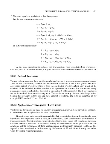
f) The rotor equations involving the flux linkages are:-
For the synchronous machine rotor
v f = R f i f + pψ f
0 = R kd · i kd + pψ kd
0 = R kq · i kq + pψ kq
v f = R f i f + pL fd i f + pM d i d + pM d i kd
0 = R kd · i kd + pL kd i kd + pM d i d + pM d i f
0 = R kq · i kq + pL kq · i kq + pM q i q
a) Induction machine rotor
0 = R kd · i kd + pψ kd
0 = R kq · i kq + pψ kq
0 = R kd · i kd + pL kd · i kd + pM d i d
0 = R kq · i kq + pL kq · i kq + pM q i q
At this stage operational impedances and time constants have been derived for synchronous
machines, and for induction machines, if appropriate substitutions are made as shown in Reference 23.
20.3.1 Derived Reactances
The derived reactances are those most frequently used to specify synchronous generators and motors.
They are the synchronous, transient and sub-transient reactances in the d and q-axes. The most
convenient method of deriving these is from the application of a three-phase short circuit at the
terminals of the unloaded machine, whether it be a generator or a motor. For a motor the testing
procedure is more complicated as described in sub-section 5 of Reference 23. The d-axis reactances
are easily obtained from normal factory tests. The q-axis are usually taken as their design values
because the necessary factory tests are more difficult to perform. The tests are described in for
example IEEE standard 112 and BS4296.
20.3.2 Application of Three-phase Short Circuit
The following derivations are made for a synchronous generator, after which the derivations applicable
to induction motors are given by a heuristic comparison.
Generators and motors are often connected to their associated switchboards or networks by an
impedance. This impedance can be a cable, an overhead line, a unit transformer or a combination of
these components. The intermediate circuit introduced in the stator circuit will contain resistance and
inductive reactance, the effect of which is to modify the time constants in the generator and motor
equations, and the performance of these machines under most transiently disturbed conditions. This
aspect has been mentioned in the literature e.g. References 24, 25 and 26 but is easily overlooked
when developing computer programs.