
Page 506 - Handbook of Electrical Engineering
P. 506
496 HANDBOOK OF ELECTRICAL ENGINEERING
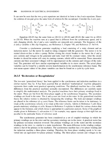
It can now be seen that the two q-axis equations are identical in form to the d-axis equations. Hence
the solution of one pair gives the same form of solution for the second pair. Consider the d-axis pair:-
X d ω X md ω
R a + jω (1 − s) jω (1 − s)
X dq X md
V d ω n ω n ω n ω n I d
=
0 X md X k I kd
p 0 R k + jω 0
ω n ω n
Equation (20.25) has the same form as (20.12) to (20.16) and (20.21) the same for as (20.6)
to (20.10). When the machine runs at a speed that is different from the synchronous speed, and is
only changing slowly, the d and q axis variables are sinusoids not constants. The frequency of the
d and q variables is the slip frequency, see Reference 3, Chapter VII, and Reference 27 Art 6-6.
Consider a synchronous generator supplying a load consisting of a static element and an
induction motor. Let the motor be small in rating compared with the generator. The motor is to be
started direct-on-line to drive a pump. Before closing the circuit breaker to the motor the d and q
axis currents and voltages in the generator and static load will be constant values. After the circuit
breaker is closed the motor will carry its starting currents, which will be sinusoidal. These sinusoidal
currents and their associated voltages will be superimposed on the currents and voltages of the static
load. The generator will have similar superimposed variables in its stator circuits. The actual phase
variables can be found by a suitable inverse transformation in the synchronous reference frame. The
root-mean-square values of the phase variables can then be found on a cycle-by-cycle basis.
20.3.5 ‘Re-iteration or Recapitulation’
The two-axis ‘generalised theory’ has been applied to the synchronous and induction machines in a
similar manner thus far. It has been assumed that an idealised ‘mathematical’ machine adequately
represents them under most practical operating conditions. The idealised machine has a few subtle
differences from the practical machines normally encountered. The differences are carefully made
to simplify the mathematical analysis. The practical machines have their primary windings fixed in
the stator. These are fed from the three-phase supply at the synchronous frequency. The secondary
windings are fixed in the rotor. The d and q-axes are fixed on the rotor. In the generalised machine
theory the relative motion is obtained by transposing the windings. The field and damper windings
are placed in the reference (d –q axes) frame. The reference frame can be taken to be stationary, to
rotate at the synchronous velocity or to rotate at the rotor velocity. Adkins in Reference 3 calls these
pseudo-stationary windings or coils. Krause in Reference 5 explains in detail the various choices that
appear in the literature, and which choice is appropriate to a particular analysis. Some of the graphical
results given in Reference 5, sub-section 4.11 for example, may appear strange at first sight but are
peculiar to the particular frame of reference used.
The synchronous generator has been considered as a set of coupled windings in which the
primary windings are in the rotor and the secondary windings are in the stator. A practical motor has
the primary-secondary notation reversed. The primary windings are in the stator and the secondary
windings in the rotor, i.e. similar to a static transformer. The main difference in the winding configu-
ration is that of the primary in the machines. The synchronous machine has a two-phase winding and
the induction machine a three-phase winding. Therefore the three-phase winding needs to be con-
verted into an equivalent two-phase primary winding. The three-phase currents and voltages in the