
Page 88 - Handbook of Energy Engineering Calculations
P. 88
REGENERATIVE BLEED-STEAM CYCLE GENERAL
ENERGY ANALYSIS
Sketch the cycle layout, T-S diagram, and energy-flow chart for a
regenerative bleed-steam turbine plant having three feedwater heaters and
four feed pumps. Write the equations for the work-output available energy
and the energy rejected to the condenser.
Calculation Procedure:
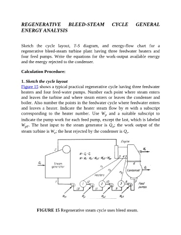
1. Sketch the cycle layout
Figure 15 shows a typical practical regenerative cycle having three feedwater
heaters and four feed-water pumps. Number each point where steam enters
and leaves the turbine and where steam enters or leaves the condenser and
boiler. Also number the points in the feedwater cycle where feedwater enters
and leaves a heater. Indicate the heater steam flow by m with a subscript
corresponding to the heater number. Use W and a suitable subscript to
p
indicate the pump work for each feed pump, except the last, which is labeled
W . The heat input to the steam generator is Q ; the work output of the
pF
a
steam turbine is W ; the heat rejected by the condenser is Q .
e
r
FIGURE 15 Regenerative steam cycle uses bleed steam.