
Page 116 - Handbook of Materials Failure Analysis
P. 116
7 Applications 111
700 kN 700 kN
A
F
400
A
1600
A
400
A
1800
B B B B
C
400
900 400 C 3100 400 900
Dimensions in millimeters
Section AA: Section BB:
4f20 4f20 Section CC:
40 50 60
320 400 300 400 280 22f20 400
40 50 60
300 300 800
4f20 4f20
Stirrups: Stirrups: Stirrups:
f10 c/ 125 f10 c/ 125 f10 c/ 250
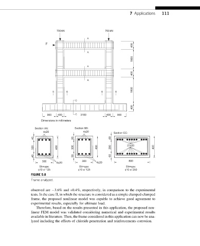
FIGURE 5.8
Frame analyzed.
observed are 3.6% and +0.4%, respectively, in comparison to the experimental
tests. In the case II, in which the structure is considered as a simple clamped-clamped
frame, the proposed nonlinear model was capable to achieve good agreement to
experimental results, especially for ultimate load.
Therefore, based on the results presented in this application, the proposed non-
linear FEM model was validated considering numerical and experimental results
available in literature. Then, the frame considered in this application can now be ana-
lyzed including the effects of chloride penetration and reinforcements corrosion.