
Page 132 - Handbook of Materials Failure Analysis
P. 132
128 CHAPTER 6 Failure analysis of concrete sleepers/bearers
Dip angle, 2a
Wheel trajectory
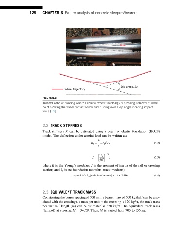
FIGURE 6.3
Transfer zone at crossing where a conical wheel traversing a v-crossing (removal of white
paint showing the wheel contact band) and running over a dip angle inducing impact
force [1,2].
2.2 TRACK STIFFNESS
Track stiffness K t can be estimated using a beam on elastic foundation (BOEF)
model. The deflection under a point load can be written as:
P
3
K t ¼ ¼ 8β EI; (6.2)
y
1=4
k f
β ¼ ; (6.3)
4EI
where E is the Young’s modulus; I is the moment of inertia of the rail or crossing
section; and k f is the foundation modulus (track modulus).
k f ¼ 4:104P 0 axle loadintonsÞ +14:61MPa: (6.4)
ð
2.3 EQUIVALENT TRACK MASS
Considering the bearer spacing of 600 mm, a bearer mass of 600 kg (half can be asso-
ciated with the crossing), a mass per unit of the crossing is 120 kg/m, the track mass
per unit rail length (m) can be estimated as 620 kg/m. The equivalent track mass
(lumped) at crossing M t ¼3m/2β. Thus, M t is varied from 705 to 756 kg.