
Page 168 - Handbook of Materials Failure Analysis
P. 168
164 CHAPTER 7 Investigation of failure behavior of tubular components
Table 7.1 Chemical Compositions of Zircaloy-4
Element Sn (%) Fe (%) Cr (%) Ni (%) O (%) Zr (%)
wt% 1.50 0.21 0.10 0.007 0.12 Balance
hexagonally closed packed (HCP) crystals are concentrated at about 30° from
the radial direction of the tube. The micro-structure also contains Laves phases of
Zr(Fe,Cr) 2 type which are considered as inclusions. After the pilgering process,
stress relieving heat treatment is carried out at 480 °C for 3.5 h. This relaxes the
residual stresses. However, the grain micro-structure remains intact.
3 EXPERIMENT ON RING SPECIMENS FOR EVALUATION
OF TRANSVERSE MECHANICAL PROPERTIES
Several specimens in the shape of rings of 3 mm width approximately were
machined from the unirradiated stress-relief annealed (SRA) Zircaloly-4 fuel pins
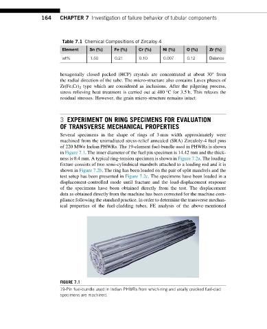
of 220 MWe Indian PHWRs. The 19-element fuel-bundle used in PHWRs is shown
in Figure 7.1. The inner diameter of the fuel pin specimen is 14.42 mm and the thick-
ness is 0.4 mm. A typical ring-tension specimen is shown in Figure 7.2a. The loading
fixture consists of two semi-cylindrical mandrels attached to a loading rod and it is
shown in Figure 7.2b. The ring has been loaded on the pair of split mandrels and the
test setup has been presented in Figure 7.2c. The specimens have been loaded in a
displacement-controlled mode until fracture and the load-displacement response
of the specimens have been obtained directly from the test. The displacement
data as obtained directly from the machine has been corrected for the machine com-
pliance following the standard practice. In order to determine the transverse mechan-
ical properties of the fuel-cladding tubes, FE analysis of the above-mentioned
FIGURE 7.1
19-Pin fuel-bundle used in Indian PHWRs from which ring and axially cracked fuel-clad
specimens are machined.