
Page 173 - Handbook of Materials Failure Analysis
P. 173
5 Fracture Experiment on Tubular Specimens 169
Ø28.88
0.20
30
25
110
50
8.00°
110
Ø14.42
Ø15.22
Ø13.50
All dimensions are in mm
(a) (b)
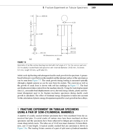
FIGURE 7.6
Geometry of (a) the conical loading mandrel with half angle of 4° for the conical part and
(b) the axially cracked fuel-clad specimen with internal diameter 14.42 mm, thickness
0.4 mm, length 50 mm, a 0 /W ratio 0.5.
initialcrack-tipbluntingandsubsequentductilecrackgrowthinthespecimen.Agrease-
based lubricant is used between the mandrel and the internal surface of the specimen as
can beseenfrom Figure 7.7. The crack growth during loading is measured optically
(through a digital camera) as can be seen from the picture. The crack-tip as well as
the growth of crack front is shown with red line markings in Figure 7.7. The load
and displacement data is taken from the machine directly. Using the load-displacement
data (i.e.,areaunder load-displacement curve), the total energy(elastic, plastic and fric-
tional dissipation) used in the fracture-mechanics specimens during ductile crack
growth is calculated. The effect of frictional energy dissipation is taken into account
forthecalculationofplasticenergydissipationrequiredforcrackgrowthinthesealloys.
5 FRACTURE EXPERIMENT ON TUBULAR SPECIMENS
USING A PAIR OF SEMI-CYLINDRICAL MANDRELS
A number of axially cracked tubular specimens have been machined from the as-
received fuel pins. Co-axial cracks of various sizes have been machined on these
specimens and the specimens have been subjected to fatigue pre-cracking so as to
create sharp initial cracks. The tubes are of 14.42 mm inner diameter, 0.4 mm thick-
ness, and 13 mm length. A typical axially cracked fuel pin specimen is shown in
Figure 7.8a. The loading fixture consists of a pair of split semi-cylindrical mandrels