
Page 175 - Handbook of Materials Failure Analysis
P. 175
5 Fracture Experiment on Tubular Specimens 171
W
a 0
Specimen
Fixture
Load
(a) (b)
FIGURE 7.8
(a) An axially cracked specimen machined from fuel-clad tube; (b) specimen loaded with two
semi-cylindrical mandrels to open the crack.
0.25 b
Ø 14.3± 0.03
1 to 7
18± 0.04
13
2
W
0.5
D i
All dimensions are in mm
(a) (b)
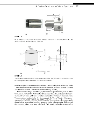
FIGURE 7.9
Dimensions of (a) an axially cracked specimen machined from fuel-clad tube (D i ¼15.2 mm);
(b) semi-cylindrical split mandrels (b¼8 mm, w¼19 mm).
used for compliance measurements as a function of crack length to width (a/W)ratio.
These compliance data has been later to used to derive the geometric or shape functions
for derivation of mode-I linear elastic stress intensity factor K I .
Theinitialcracklengthtowidth(a 0 /W)ratiosofthesespecimensaregivenas:0.474,
0.526,0.579,0.632,0.684,0.737,and 0.789,respectively. Later, another set ofsix spec-
imens with very close a 0 /W ratios have been prepared for the fracture-mechanics tests.
These specimens are denoted as Sp1-Sp6, respectively. The a 0 /W ratios of these spec-
imens are 0.569, 0.554, 0.595, 0.570, 0.554, and 0.570, respectively. The crack lengths
during fatigue pre-cracking have been measured at nine points along the thickness and
their average values have been calculated. Each specimen has been subjected to