
Page 180 - Handbook of Materials Failure Analysis
P. 180
176 CHAPTER 7 Investigation of failure behavior of tubular components
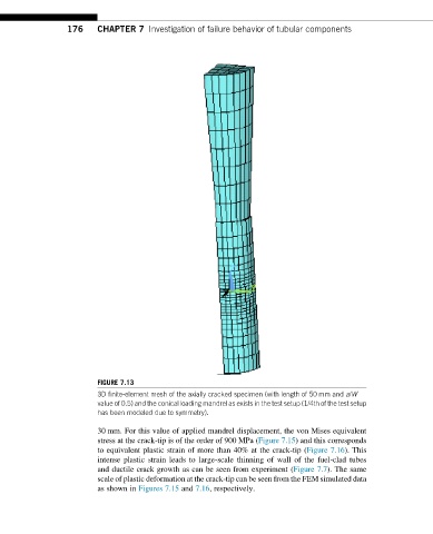
FIGURE 7.13
3D finite-element mesh of the axially cracked specimen (with length of 50 mm and a/W
value of 0.5) and the conical loading mandrel as exists in the test setup (1/4th of the test setup
has been modeled due to symmetry).
30 mm. For this value of applied mandrel displacement, the von Mises equivalent
stress at the crack-tip is of the order of 900 MPa (Figure 7.15) and this corresponds
to equivalent plastic strain of more than 40% at the crack-tip (Figure 7.16). This
intense plastic strain leads to large-scale thinning of wall of the fuel-clad tubes
and ductile crack growth as can be seen from experiment (Figure 7.7). The same
scale of plastic deformation at the crack-tip can be seen from the FEM simulated data
as shown in Figures 7.15 and 7.16, respectively.