
Page 178 - Handbook of Materials Failure Analysis
P. 178
174 CHAPTER 7 Investigation of failure behavior of tubular components
The elastic part is calculated from the expression of linear elastic stress intensity factor
K I (thecrack-tipissubjectedtomode-Iloading)fortheplanestressconditionasfollows.
2
J el ¼ K =E (7.3)
I
where E is the Young’s modulus of elasticity (90 GPa for this material at room tem-
perature). The stress intensity factor K I depends upon applied load P, thickness t,
crack length a, width W, and geometry of the specimen and is written as
P
K I ¼ p ffiffiffiffiffi fa=Wð Þ (7.4)
2t W
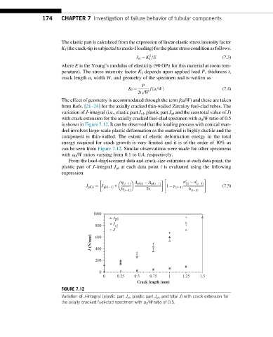
The effect of geometry is accommodated through the term f(a/W) and these are taken
from Refs. [21–24] for the axially cracked thin-walled Zircaloy fuel-clad tubes. The
variation of J-integral (i.e., elastic part J el , plastic part J pl and the sum total value of J)
with crack extension for the axially cracked fuel-clad specimen with a 0 /W ratio of 0.5
is shown in Figure 7.12. It can be observed that the loading process with conical man-
drel involves large-scale plastic deformation as the material is highly ductile and the
component is thin-walled. The extent of elastic deformation energy in the total
energy required for crack growth is very limited and it is of the order of 10% as
can be seen from Figure 7.12. Similar observations were made for other specimens
with a 0 /W ratios varying from 0.1 to 0.4, respectively.
From the load-displacement data and crack-size estimates at each data point, the
plastic part of J-integral J pl at each data point i is evaluated using the following
expression
η a a
" 0 0 #
ð
Þ + ð i 1Þ A pl iðÞ A pl i 1Þ 1 γ i ðÞ ð i 1Þ (7.5)
J pl iðÞ ¼ J pl i 1ð ð i 1Þ
b i 1Þ 2t b i 1Þ
ð ð
1000
J pl
J
800 el
J
J (N/mm) 600
400
200
0
0 0.25 0.5 0.75 1 1.25 1.5
Crack length (mm)
FIGURE 7.12
Variation of J-integral (elastic part J el , plastic part J pl , and total J) with crack extension for
the axially cracked fuel-clad specimen with a 0 /W ratio of 0.5.