
Page 174 - Handbook of Materials Failure Analysis
P. 174
170 CHAPTER 7 Investigation of failure behavior of tubular components
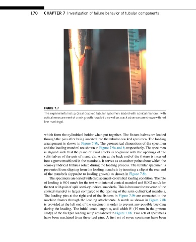
FIGURE 7.7
The experimental setup (axial cracked tubular specimen loaded with conical mandrel) with
optical measurement of crack growth (crack-tip as well as crack advances are shown with red
line markings).
which form the cylindrical holder when put together. The fixture halves are loaded
through the pins after being inserted into the tubular cracked specimen. The loading
arrangement is shown in Figure 7.8b. The geometrical dimensions of the specimen
and the loading mandrel are shown in Figure 7.9a and b, respectively. The specimen
is aligned such that the plane of axial cracks is co-planar with the openings of the
split-halves of the pair of mandrels. A pin at the back end of the fixture is inserted
into a grove machined in the mandrels. It serves as an anchor point about which the
semi-cylindrical fixtures rotate during the loading process. The tubular specimen is
prevented from slipping from the loading mandrels by inserting a clip at the rear end
of the mandrels (opposite to loading groves) as shown in Figure 7.8b.
The specimens are tested with displacement-controlled loading condition. The rate
of loading is 0.01 mm/s for the test with internal conical mandrel and 0.002 mm/s for
the test with pair of split semi-cylindrical mandrels. This is because the traverse of the
conical mandrel is larger compared to the opening of the semi-cylindrical mandrels.
The loading pins at the right end of the fixtures in Figure 7.9b are connected to the
machine frames through the loading attachments. A notch as shown in Figure 7.8b
is provided at the left end of the specimen in order to prevent any possible buckling
during the loading. The initial crack length a 0 and width W (19 mm in the present
study) of the fuel pin loading setup are labeled in Figure 7.8b. Two sets of specimens
have been machined from these fuel pins. A first set of seven specimens have been