
Page 170 - Handbook of Materials Failure Analysis
P. 170
166 CHAPTER 7 Investigation of failure behavior of tubular components
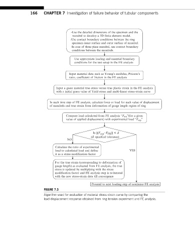
-Use the detailed dimensions of the specimen and the
mandrel to develop a 3D finite element model.
-Use contact boundary conditions between the ring
specimen inner surface and outer surface of mandrel.
-In case of three-piece mandrel, use contact boundary
conditions between the mandrels.
Use appropriate loading and essential boundary
conditions for the test setup in the FE analysis
Input material data such as Young’s modulus, Poisson’s
ratio, coefficient of friction in the FE analysis
Input a guess material true stress versus true plastic strain in the FE analysis
with a initial guess value of Yield stress and multi-linear stress-strain curve
In each time step of FE analysis, calculate force or load for each value of displacement
of mandrels and true strain from deformation of gauge length region of ring
Compare load calculated from FE analysis “F ”(for a given
FE
value of applied displacement) with experimental load “F exp ”
Is |(F exp −F FE )| < d
(d: specified tolerance)
NO
Calculate the ratio of experimental
load to calculated load and define YES
it as a stress modification factor
For the true strain (corresponding to deformation of
gauge length) as evaluated from FE analysis, the true
stress is updated by multiplying with the stress
modification factor and FE analysis step is re-iterated
with the new stress-strain data till convergence
Proceed to next loading step of nonlinear FE analysis
FIGURE 7.3
Algorithm used for evaluation of material stress-strain curve by comparing the
load-displacement response obtained from ring-tension experiment and FE analysis.