
Page 183 - Handbook of Materials Failure Analysis
P. 183
6 Results and Discussion 179
ICM specimen, Zircaloy-4
(ID = 14.22 mm, th = 0.4 mm, length = 50 mm, a/W = 0.5)
6000
exp.
5000 FE analysis (µ = 0.08)
f
Load (N) 4000
3000
2000
1000
0
0 5 10 15 20 25 30 35 40 45 50
Displacement (mm)
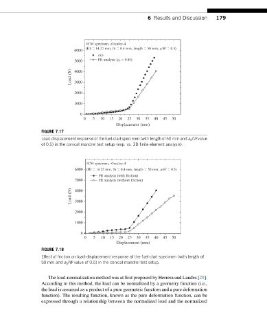
FIGURE 7.17
Load-displacement response of the fuel-clad specimen (with length of 50 mm and a 0 /W value
of 0.5) in the conical mandrel test setup (exp. vs. 3D finite-element analysis).
ICM specimen, Zircaloy-4
6000 (ID = 14.22 mm, th = 0.4 mm, length = 50 mm, a/W = 0.5)
FE analysis (with friction)
5000 FE analysis (without friction)
Load (N) 4000
3000
2000
1000
0
0 5 10 15 20 25 30 35 40 45 50
Displacement (mm)
FIGURE 7.18
Effect of friction on load-displacement response of the fuel-clad specimen (with length of
50 mm and a 0 /W value of 0.5) in the conical mandrel test setup.
The load-normalization method was at first proposed by Herrera and Landes [29].
According to this method, the load can be normalized by a geometry function (i.e.,
the load is assumed as a product of a pure geometric function and a pure deformation
function). The resulting function, known as the pure deformation function, can be
expressed through a relationship between the normalized load and the normalized