
Page 273 - Handbook of Materials Failure Analysis
P. 273
5 Case Study of Verification Specification: Robotics 269
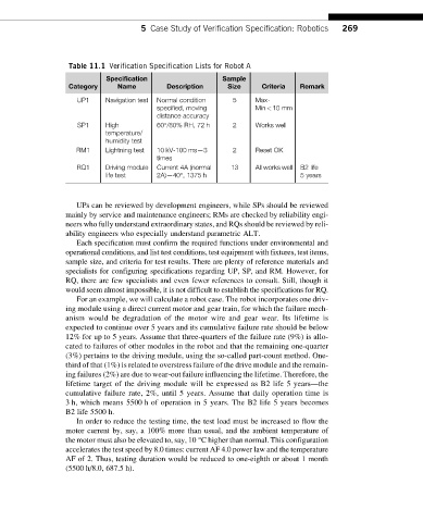
Table 11.1 Verification Specification Lists for Robot A
Specification Sample
Category Name Description Size Criteria Remark
UP1 Navigation test Normal condition 5 Max-
specified, moving Min<10 mm
distance accuracy
SP1 High 60°/80% RH, 72 h 2 Works well
temperature/
humidity test
RM1 Lightning test 10 kV-100 ms—3 2 Reset OK
times
RQ1 Driving module Current 4A (normal 13 All works well B2 life
life test 2A)—40°, 1375 h 5 years
UPs can be reviewed by development engineers, while SPs should be reviewed
mainly by service and maintenance engineers; RMs are checked by reliability engi-
neers who fully understand extraordinary states, and RQs should be reviewed by reli-
ability engineers who especially understand parametric ALT.
Each specification must confirm the required functions under environmental and
operational conditions, and list test conditions, test equipment with fixtures, test items,
sample size, and criteria for test results. There are plenty of reference materials and
specialists for configuring specifications regarding UP, SP, and RM. However, for
RQ, there are few specialists and even fewer references to consult. Still, though it
would seem almost impossible, it is not difficult to establish the specifications for RQ.
For an example, we will calculate a robot case. The robot incorporates one driv-
ing module using a direct current motor and gear train, for which the failure mech-
anism would be degradation of the motor wire and gear wear. Its lifetime is
expected to continue over 5 years and its cumulative failure rate should be below
12% for up to 5 years. Assume that three-quarters of the failure rate (9%) is allo-
cated to failures of other modules in the robot and that the remaining one-quarter
(3%) pertains to the driving module, using the so-called part-count method. One-
third of that (1%) is related to overstress failureof thedrivemoduleand theremain-
ing failures (2%) are due to wear-out failure influencing the lifetime. Therefore, the
lifetime target of the driving module will be expressed as B2 life 5 years—the
cumulative failure rate, 2%, until 5 years. Assume that daily operation time is
3 h, which means 5500 h of operation in 5 years. The B2 life 5 years becomes
B2 life 5500 h.
In order to reduce the testing time, the test load must be increased to flow the
motor current by, say, a 100% more than usual, and the ambient temperature of
the motor must also be elevated to, say, 10 °C higher than normal. This configuration
accelerates the test speed by 8.0 times: current AF 4.0 power law and the temperature
AF of 2. Thus, testing duration would be reduced to one-eighth or about 1 month
(5500 h/8.0, 687.5 h).