
Page 358 - Handbook of Materials Failure Analysis
P. 358
356 CHAPTER 14 Fatigue failure analysis of welded structures
or structure, and the word “fluctuating” means that the loading associated with
fatigue is alternating rather than being stationary [1].
Although the number of mechanical failures cases is low when compared to suc-
cessful components and structures, the cost associated with the failures is over-
whelming. A comprehensive study was carried out in 1982 to estimate the cost of
fractures in the United States. This study shows that the restitution of mechanical
fractures in 1 year was $119 billion, which could have been decreased significantly
using appropriate engineering designs, including fatigue design [3].
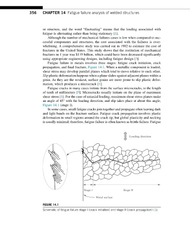
Fatigue failure in metals involves three stages: fatigue crack initiation, crack
propagation, and final fracture, Figure 14.1. When a metallic component is loaded,
shear stress may develop parallel planes which tend to move relative to each other.
Slip plastic deformation happens when a plane slides against adjacent planes within a
grain. As they are the weakest, surface grains are more prone to slip plastic defor-
mation, which produces a microcrack [4].
Fatigue cracks in many cases initiate from the surface microcracks, to the length
of tenth of millimeters [5]. Microcracks usually initiate on the plane of maximum
shear stress [1]. For the case of uniaxial loading, maximum shear stress planes make
an angle of 45° with the loading direction, and slip takes place at about this angle,
Figure 14.1 (stage I).
In some cases, small fatigue cracks join together and propagate often leaving dark
and light bands on the fracture surface. Fatigue crack propagation involves plastic
deformation in small regions around the crack tip, but global plasticity and necking
is usually minimal; therefore, fatigue failure is often known as brittle failure. Fatigue
Loading direction
Stage I Stage II
Metal surface
FIGURE 14.1
Schematic of fatigue failure stage I (crack initiation) and stage II (crack propagation) [1].