
Page 363 - Handbook of Materials Failure Analysis
P. 363
2 Fatigue Modeling of Welded Structures by Local Approaches 361
The fracture mechanics approach considers a measure of SIF or J-integral as the
fatigue damage parameter, and relates this parameter to the fatigue life or the crack-
growth rate. Pook [14], Swellam et al. [15], and Wang et al. [33] proposed different
methods for calculating the SIF or J-integral range for spot-welds.
Swellam in 1992 [15] proposed a fatigue model for predicting crack propagation
life for spot-welds based on the fracture mechanics approach. In this model, the
effects of modes I and II loading were taken into account. The spot-weld was con-
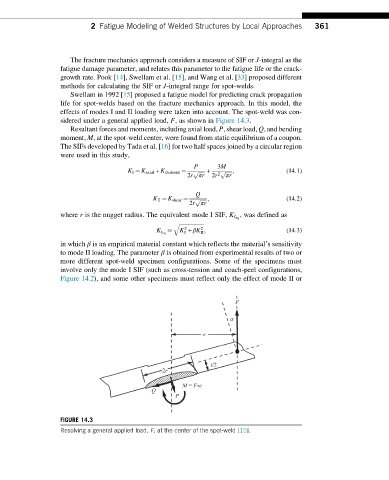
sidered under a general applied load, F, as shown in Figure 14.3.
Resultant forces and moments, including axial load, P, shear load, Q, and bending
moment, M, at the spot-weld center, were found from static equilibrium of a coupon.
The SIFs developed by Tada et al. [16] for two half spaces joined by a circular region
were used in this study,
P 3M
K I ¼ K axial + K moment ¼ p ffiffiffiffiffi + p ffiffiffiffiffi; (14.1)
2r πr 2r 2 πr
Q
K II ¼ K shear ¼ p ffiffiffiffiffi; (14.2)
2r πr
, was defined as
where r is the nugget radius. The equivalent mode I SIF, K I eq
q ffiffiffiffiffiffiffiffiffiffiffiffiffiffiffiffiffiffi
2
2
¼ K + βK ; (14.3)
K I eq I II
in which β is an empirical material constant which reflects the material’s sensitivity
to mode II loading. The parameter β is obtained from experimental results of two or
more different spot-weld specimen configurations. Some of the specimens must
involve only the mode I SIF (such as cross-tension and coach-peel configurations,
Figure 14.2), and some other specimens must reflect only the effect of mode II or
F
a
e
t/2
2r
M = F •e
Q
P
FIGURE 14.3
Resolving a general applied load, F, at the center of the spot-weld [15].