Page 365 - Handbook of Materials Failure Analysis
P. 365

2 Fatigue Modeling of Welded Structures by Local Approaches   363


                  fracture mechanics-based models, often provides enough flexibility to be applicable
                  to different specimens and structures. Therefore, these models are widely employed
                  in industry, including the automobile industry [9]. However, some weak points are
                  also associated with this approach. A serious shortcoming is that the notch effect at
                  the spot-weld edge is ignored [9].
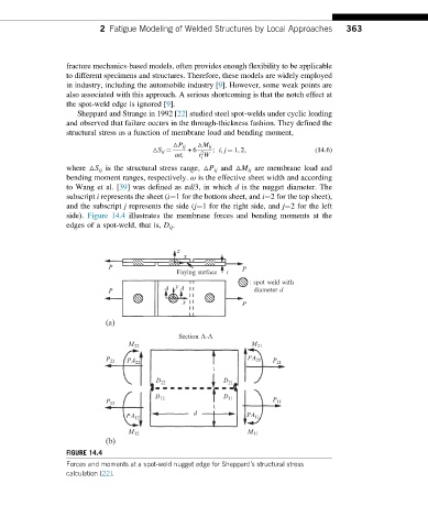
                     Sheppard and Strange in 1992 [22] studied steel spot-welds under cyclic loading
                  and observed that failure occurs in the through-thickness fashion. They defined the
                  structural stress as a function of membrane load and bending moment,

                                             △P ij  △M ij
                                       △S ij ¼  +6  2  ; i, j ¼ 1, 2;           (14.6)
                                             ωt i  t W
                                                    i
                  where △S ij is the structural stress range, △P ij and △M ij are membrane load and
                  bending moment ranges, respectively. ω is the effective sheet width and according
                  to Wang et al. [39] was defined as πd/3, in which d is the nugget diameter. The
                  subscript i represents the sheet (i¼1 for the bottom sheet, and i¼2 for the top sheet),
                  and the subscript j represents the side (j¼1 for the right side, and j¼2 for the left
                  side). Figure 14.4 illustrates the membrane forces and bending moments at the
                  edges of a spot-weld, that is, D ij .


                                              z
                                               x
                            P                                 P
                                             Faying surface  t
                                                                : spot weld with
                                          A  y A
                            P                                     diameter d
                                               x              P

                            (a)
                                              Section A-A
                                 M 22                           M 21
                            P 22  PA 22                        PA 21  P 21
                                                       t
                                        D 22             D 21
                                        D 12             D 11
                            P 12                                      P 11
                                                       t
                                 PA 12            d            PA 11

                                 M 12                          M 11
                            (b)
                  FIGURE 14.4
                  Forces and moments at a spot-weld nugget edge for Sheppard’s structural stress
                  calculation [22].
   360   361   362   363   364   365   366   367   368   369   370