
Page 41 - Handbook of Materials Failure Analysis
P. 41
34 CHAPTER 2 Failure analysis in chemical industries
Isometric drawing
of drainage caustic line
Over head
road crossing
N E Spent caustic 23 M 1.M raise of
storage tank pipe line
W 930 TK 5
4 Dia
2 M 58.M
10.7 M 1.75
Defective potron
5.3
40.0 M
2.3 M 1 M
85.M
40.0 M
4 Dia Intermittent flow
8-10 m 3 /hr
4 Dla
To tank
from area 500
RCC
Ground
69.0 M support support
4 Dla 1.5 Dla Continuous flow
1.0~2.0 m 3 /hr GROUND
from area 400
Blind
1.0 M
4 Dla
No flow from
area 300
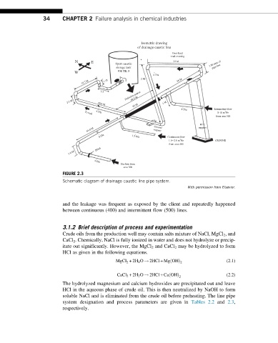
FIGURE 2.3
Schematic diagram of drainage caustic line pipe system.
With permission from Elsevier.
and the leakage was frequent as exposed by the client and repeatedly happened
between continuous (400) and intermittent flow (500) lines.
3.1.2 Brief description of process and experimentation
Crude oils from the production well may contain salts mixture of NaCl, MgCl 2 , and
CaCl 2 . Chemically, NaCl is fully ionized in water and does not hydrolyze or precip-
itate out significantly. However, the MgCl 2 and CaCl 2 may be hydrolyzed to form
HCl as given in the following equations.
ð
MgCl +2H 2 O ! 2HCl + Mg OHÞ (2.1)
2 2
CaCl 2 +2H 2 O ! 2HCl + Ca OHð Þ 2 (2.2)
The hydrolyzed magnesium and calcium hydroxides are precipitated out and leave
HCl in the aqueous phase of crude oil. This is then neutralized by NaOH to form
soluble NaCl and is eliminated from the crude oil before preheating. The line pipe
system designation and process parameters are given in Tables 2.2 and 2.3,
respectively.