
Page 42 - Handbook of Materials Failure Analysis
P. 42
3 Case Studies 35
Table 2.2 Spent Caustic Drainage Line Pipe System Designations
3
Designation Flow Conditions Pipe Dimensions (in.) Flow Rate (m /h)
NFL-300 No flow 4 –
CFL-400 Continuous 1.5 1.0-2.0
IFL-500 Intermittent 4 8.0-10.0
With permission from Elsevier.
Table 2.3 Process Parameters and Materials Specifications
Parameter Value
Line service Spent caustic
Total alkalinity 0.90%
pH 8.3
Temperature 38 °C
3
Average flow rate 1.2-2.0 m /h
Pipe 4 in. (ASTM A53 Gr B)
With permission from Elsevier.
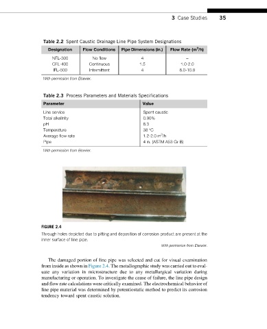
FIGURE 2.4
Through holes depicted due to pitting and deposition of corrosion product are present at the
inner surface of line pipe.
With permission from Elsevier.
The damaged portion of line pipe was selected and cut for visual examination
from inside as shown in Figure 2.4. The metallographic study was carried out to eval-
uate any variation in microstructure due to any metallurgical variation during
manufacturing or operation. To investigate the cause of failure, the line pipe design
and flow rate calculations were critically examined. The electrochemical behavior of
line pipe material was determined by potentiostatic method to predict its corrosion
tendency toward spent caustic solution.