
Page 43 - Handbook of Materials Failure Analysis
P. 43
36 CHAPTER 2 Failure analysis in chemical industries
3.1.3 Visual observations and testing
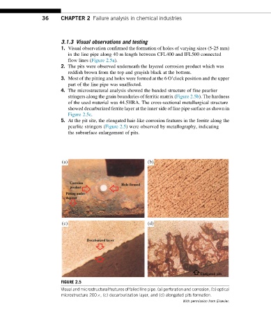
1. Visual observation confirmed the formation of holes of varying sizes (5-25 mm)
in the line pipe along 40 m length between CFL400 and IFL500 connected
flow lines (Figure 2.5a).
2. The pits were observed underneath the layered corrosion product which was
reddish brown from the top and grayish black at the bottom.
3. Most of the pitting and holes were formed at the 6 O’clock position and the upper
part of the line pipe was unaffected.
4. The microstructural analysis showed the banded structure of fine pearlier
stringers along the grain boundaries of ferritic matrix (Figure 2.5b). The hardness
of the used material was 44.5HRA. The cross-sectional metallurgical structure
showed decarburized ferrite layer at the inner side of line pipe surface as shown in
Figure 2.5c.
5. At the pit site, the elongated hair-like corrosion features in the ferrite along the
pearlite stringers (Figure 2.5) were observed by metallography, indicating
the subsurface enlargement of pits.
(a) (b)
(c) (d)
FIGURE 2.5
Visual and microstructural features of failed line pipe. (a) perforation and corrosion, (b) optical
microstructure 200 , (c) decarburization layer, and (d) elongated pits formation.
With permission from Elsevier.