
Page 44 - Handbook of Properties of Textile and Technical Fibres
P. 44
Testing and characterization of fibers 25
By replacing the glass slide by a water bowl, Cottonscope Pty Ltd proposes today
the “diamscope” as a dedicated fiber diameter and length measurement “high-
definition” equipment. Thanks to an improved dispersion and a dedicated image anal-
ysis technology, fiber diameters from 0.5 to 50 mm can be processed. Animal, cotton,
glass, ceramic, and synthetic microfibers can be easily characterized up to 20,000
fibers per minute (Brims and Hwang, 2015).
While pursuing the objective of obtaining the diameter (or apparent diameter) dis-
tribution of a population of fibers, a direct measurement of cross-sectional areas could
sometimes be more instructive. A bundle of the fibers can be embedded in a suitable
resin such as epoxy resin, then sectioned and polished to examine the cross sections of
the fibers with an optical microscope in the reflection mode. The cross-sectional area
can then be estimated. Using the contrast between features and background, the image
analyzer indeed allows a quantitative evaluation of the fibers seen in a field of view.
This technique also makes it possible to ascertain the regularity of the fiber sections.
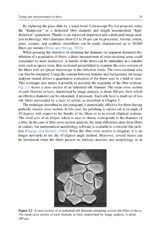
Fig. 2.1 shows a cross section of an industrial silk filament. The mean cross section
of each filament, or bave, determined by image analysis, is about 200 mm, from which
an effective diameter can be calculated, if necessary. Each silk bave is made up of two
silk fibers surrounded by a layer of sericin, as described in Chapter 5.
The technique described in this paragraph is particularly effective for fibers having
perfectly circular cross section. In this case, the polishing is carried out at an angle of
45 degrees with respect to the bundle of the fibers so as to reveal elliptical sections.
The small axis of an ellipse, which is easy to obtain, corresponds to the diameter of
a fiber. In the case of fiber cross-section analysis, the main difficulties arise from fibers
in contact, but mathematical morphology software is available to overcome this prob-
lem (Hagege and Bunsell, 1988). When the fiber cross section is irregular, it is no
longer advisable to use the 45 degrees angle method. Moreover, several biases can
be introduced when the fibers present an intricate structure and morphology as in
Figure 2.1 A cross section of an industrial silk filament containing several silk fibers or baves.
The mean cross section of each filament, or bave, determined by image analysis, is about
200 mm.