
Page 46 - Handbook of Properties of Textile and Technical Fibres
P. 46
Testing and characterization of fibers 27
n = –2
n = –1
Fiber
Intensity
Laser
L
n = 1
n = 2
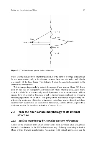
Figure 2.2 The interference pattern varies in intensity.
where L is the distance from fiber to the sensor, n is the number of fringe nodes chosen
for the measurement, DZ n is the distance between these two nth nodes, and l is the
wavelength of the laser beam. The distance L must be adjusted according to the
diameter to be measured.
This technique is particularly suitable for opaque fibers (carbon fibers, SiC fibers,
etc.). In the case of transparent and translucent fibers (thermoplastic, glass fibers,
etc.), it is advisable to coat them by metal deposition, prior to measurement, with an
opaque layer of negligible thickness, which is the technique employed for preparing
insulating specimens for the SEM. The quality of the interference fringes is very sen-
sitive to the positioning of the fiber with respect to the laser source. Several such laser
interferometry equipments are available on the market, and Dia-Stron Ltd provides a
dedicated version for the characterization of carbon fibers.
2.3 From the fiber surface morphology to its internal
structure
2.3.1 Surface morphology by scanning electron microscopy
Almost all the images of fibers which appear in this book have been taken using SEM.
Before its development in the 1960s there was no way of closely examining individual
fibers or their fracture morphologies. An analogy with optical microscopes can be