
Page 57 - Handbook of Properties of Textile and Technical Fibres
P. 57
38 Handbook of Properties of Textile and Technical Fibres
λ
λ Scattered beam
Incident beam
θθ
d
λ C
A λ /2
/2
Atomic plane θ θ
Incident angle B Reflected angle
d
Atomic plane
Figure 2.11 Bragg diffraction showing the conditions for the two waves to stay in phase after
both are reflected is that the path length ABC be a whole number (n) of wavelengths (l), or nl.
angles less than 1 degree allows larger structural units to be measured such as the long
periods in polymers. The SAXS technique requires particular equipment because of
the small angular separation of the direct beam, which is very intense and the scattered
beam. This requires large specimen to detector distances in the range of 0.5e10 m and
high-quality optical systems.
To obtain sufficiently intense patterns, it is usual to irradiate a bundle of parallel
fibers although the intense radiation from a synchrotron source allows single fibers
to be analyzed. The specimens are placed in a q 2q goniometer, as shown in
Fig. 2.12, which allows the specimen to be rotated through an azimuthal angle 4.
Quantitatively, the anisotropy of the fibers is revealed by a sequence of q 2q scans
in the azimuthal angle range 4 ( 5e90 degrees, with azimuthal increments from 2.5 to
5 degrees), as shown in Fig. 2.13 obtained with PA66 fibers. The q 2q scans ob-
tained at various azimuthal angles can be resolved into crystalline and amorphous con-
tributions using a profile fitting program based on the least-square procedure, as
illustrated in Figs. 2.13 and 2.14.
ϕ = 90°
θ 2θ
ϕ = 0°
θ 2θ
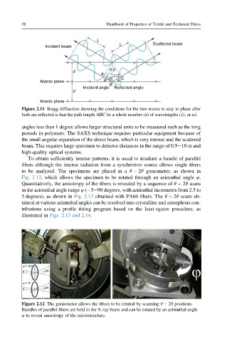
Figure 2.12 The goniometer allows the fibers to be rotated by scanning q 2q positions.
Bundles of parallel fibers are held in the X-ray beam and can be rotated by an azimuthal angle
4 to reveal anisotropy of the microstructure.