
Page 117 - Handbook of Structural Steel Connection Design and Details
P. 117
Design of Connections for Axial, Moment, and Shear Forces
102 Chapter Two
1
Use a / 2-in cap plate.
This completes the calculations required to produce the con-
nection of Fig. 2.24.
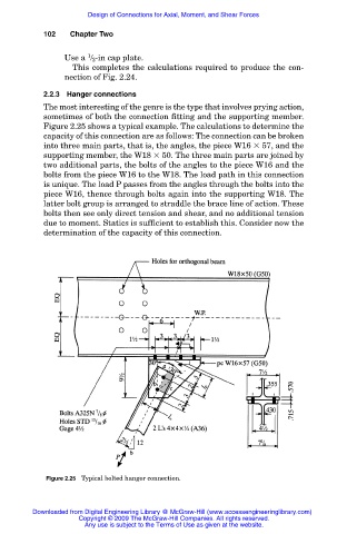
2.2.3 Hanger connections
The most interesting of the genre is the type that involves prying action,
sometimes of both the connection fitting and the supporting member.
Figure 2.25 shows a typical example. The calculations to determine the
capacity of this connection are as follows: The connection can be broken
into three main parts, that is, the angles, the piece W16 57, and the
supporting member, the W18 50. The three main parts are joined by
two additional parts, the bolts of the angles to the piece W16 and the
bolts from the piece W16 to the W18. The load path in this connection
is unique. The load P passes from the angles through the bolts into the
piece W16, thence through bolts again into the supporting W18. The
latter bolt group is arranged to straddle the brace line of action. These
bolts then see only direct tension and shear, and no additional tension
due to moment. Statics is sufficient to establish this. Consider now the
determination of the capacity of this connection.
Figure 2.25 Typical bolted hanger connection.
Downloaded from Digital Engineering Library @ McGraw-Hill (www.accessengineeringlibrary.com)
Copyright © 2009 The McGraw-Hill Companies. All rights reserved.
Any use is subject to the Terms of Use as given at the website.