
Page 200 - Handbook of Structural Steel Connection Design and Details
P. 200
Welded Joint Design and Production
Welded Joint Design and Production 185
Figure 3.2 Buttering. (Courtesy of The Lincoln Electric
Company.)
In the case of sulfur, it is possible to overcome the harmful effects of
iron sulfides by preferentially forming manganese sulfide. Manganese
sulfide (MnS) is created when manganese is present in sufficient
quantities to counteract the sulfur. Manganese sulfide has a melting
point of 2900°F. In this situation, before the weld metal begins to
solidify, manganese sulfides are formed which do not segregate. Steel
producers utilize this concept when higher levels of sulfur are encoun-
tered in the iron ore. In welding, it is possible to use filler materials
with higher levels of manganese to overcome the formation of low
melting-point iron sulfide. Unfortunately, this concept cannot be
applied to contaminants other than sulfur.
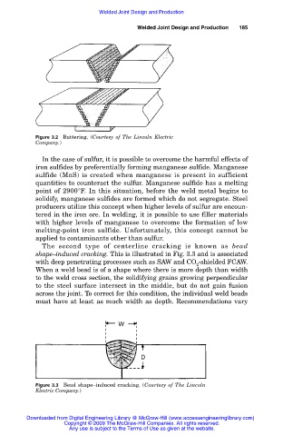
The second type of centerline cracking is known as bead
shape–induced cracking. This is illustrated in Fig. 3.3 and is associated
with deep penetrating processes such as SAW and CO -shielded FCAW.
2
When a weld bead is of a shape where there is more depth than width
to the weld cross section, the solidifying grains growing perpendicular
to the steel surface intersect in the middle, but do not gain fusion
across the joint. To correct for this condition, the individual weld beads
must have at least as much width as depth. Recommendations vary
Figure 3.3 Bead shape–induced cracking. (Courtesy of The Lincoln
Electric Company.)
Downloaded from Digital Engineering Library @ McGraw-Hill (www.accessengineeringlibrary.com)
Copyright © 2009 The McGraw-Hill Companies. All rights reserved.
Any use is subject to the Terms of Use as given at the website.