Page 119 - Hardware Implementation of Finite-Field Arithmetic
P. 119

102    Cha pte r  F o u r


                 end loop;
                 if b >= a then b := b-a; d := (d-c) mod P;
                 else
                  Old_b := b; b := a-b; a := Old_b;
                  Old_d := d; d := (c-d) mod P; c := Old_d;
                 end if;
               end loop;
               Z := c;
                  An executable  Ada file binary_algorithm.adb, including  Algo-
               rithm 4.4, is available at www.arithmetic-circuits.org.
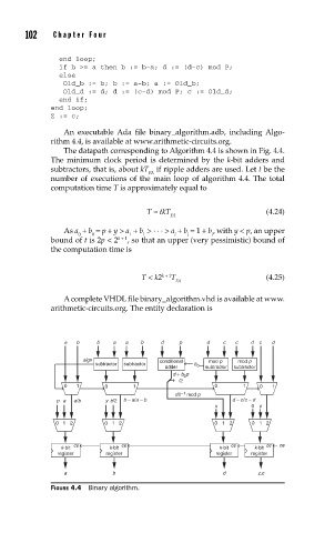
                  The datapath corresponding to Algorithm 4.4 is shown in Fig. 4.4.
               The minimum clock period is determined by the  k-bit adders and
               subtractors, that is, about kT  if ripple adders are used. Let t be the
                                       FA
               number of executions of the main loop of algorithm 4.4. The total
               computation time T is approximately equal to

                                       T ≈ tkT                      (4.24)
                                            FA
                  As a + b = p + y > a + b  >  . . .  > a + b = 1 + b , with y < p, an upper
                      0  0        1   1      i   i     i
               bound of t is 2p < 2 k + 1 , so that an upper (very pessimistic) bound of
               the computation time is


                                     T < k2 k + 1 T                 (4.25)
                                              FA
                  A  complete VHDL file binary_algorithm.vhd is available at www.
               arithmetic-circuits.org. The entity declaration is


                  a  b    b   a  a   b    d    p     d   c  c   d  c  d

                       sign               conditional  mod p  mod p
                          subtractor  subtractor  b
                                           adder   0  subtractor  subtractor
                                             d + b p
                                                0
                                              /2
                  0  1      0      1                   0      1   0  1
                                               –1
                                              d2  mod p
                pa   a/b    yb/2  b – a/a – b               d – c/c – d
                                                       x        0  c
                01 2        01 2                       01 2     01 2
                     ce         ce                         ce       ce  ce
                 k-bit       k-bit                      k-bit    k-bit
                 register    register                   register  register

                  a           b                          d        z,c
               FIGURE 4.4  Binary algorithm.
   114   115   116   117   118   119   120   121   122   123   124