
Page 426 - High Power Laser Handbook
P. 426
394 So l i d - S t at e La s e r s The National Ignition Facility Laser 395
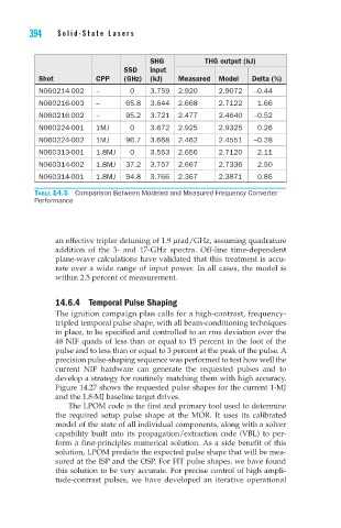
SHG THG output (kJ)
SSD input
Shot CPP (GHz) (kJ) Measured Model Delta (%)
N060214-002 – 0 3.759 2.920 2.9072 –0.44
N060216-003 – 65.8 3.644 2.668 2.7122 1.66
N060216-002 – 95.2 3.721 2.477 2.4640 –0.52
N060224-001 1MJ 0 3.672 2.925 2.9325 0.26
N060224-002 1MJ 96.7 3.668 2.462 2.4551 –0.28
N060313-001 1.8MJ 0 3.553 2.656 2.7120 2.11
N060314-002 1.8MJ 37.2 3.757 2.667 2.7336 2.50
N060314-001 1.8MJ 94.8 3.766 2.367 2.3871 0.85
Table 14.5 Comparison Between Modeled and Measured Frequency Converter
Performance
an effective tripler detuning of 1.9 μrad/GHz, assuming quadrature
addition of the 3- and 17-GHz spectra. Off-line time-dependent
plane-wave calculations have validated that this treatment is accu-
rate over a wide range of input power. In all cases, the model is
within 2.5 percent of measurement.
14.6.4 Temporal Pulse Shaping
The ignition campaign plan calls for a high-contrast, frequency-
tripled temporal pulse shape, with all beam-conditioning techniques
in place, to be specified and controlled to an rms deviation over the
48 NIF quads of less than or equal to 15 percent in the foot of the
pulse and to less than or equal to 3 percent at the peak of the pulse. A
precision pulse-shaping sequence was performed to test how well the
current NIF hardware can generate the requested pulses and to
develop a strategy for routinely matching them with high accuracy.
Figure 14.27 shows the requested pulse shapes for the current 1-MJ
and the 1.8-MJ baseline target drives.
The LPOM code is the first and primary tool used to determine
the required setup pulse shape at the MOR. It uses its calibrated
model of the state of all individual components, along with a solver
capability built into its propagation/extraction code (VBL) to per-
form a first-principles numerical solution. As a side benefit of this
solution, LPOM predicts the expected pulse shape that will be mea-
sured at the ISP and the OSP. For FIT pulse shapes, we have found
this solution to be very accurate. For precise control of high ampli-
tude-contrast pulses, we have developed an iterative operational