
Page 435 - High Power Laser Handbook
P. 435
402 So l i d - S t at e La s e r s The National Ignition Facility Laser 403
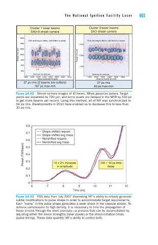
Cluster 1 lower beams Cluster 3 lower beams
SXD-B streak camera SXD streak camera
−1600
Click and drag to define right button to accept Click and drag to define right button to accept
−1400
−1500
−1200
Sweep time (ps) −1000 Sweep time (ps) −1000
−800
−600
−500
−400
Aperture for analysis Aperture for analysis
1800 2000 2200 2400 2600 2800 3000 3200 1800 2000 2200 2400 2600 2800
Warp-corrected file pixel Warp-corrected file pixel
37 ps rms (2 beams are outliers) 27 ps rms
167 ps max-min 83 ps max-min
Figure 14.42 Streak camera images of 47-beam, 88-ps gaussian pulses. Target
points are separated by 700 μm, and some quads are delayed in the MOR by 333 ps
to get more beams per record. Using this method, all of NIF was synchronized to
64 ps rms. Developments in 2010 have enabled us to decrease this to less than
30 ps rms.
0.8
Shape shifted request
0.7
Shape shifted avg meas
Nonshifted request
0.6
Nonshifted avg meas
Power (TW/beam) 0.4
0.5
0.3
10 ± 2% increase
delay
in amplitude 100 ± 10 ps time
0.2
0.1
0
6 7 8 9 10 11 12
Time (ns)
Figure 14.43 PDS data from July 2007 illustrating NIF’s ability to reliably generate
subtle modifications to pulse shape in order to accommodate target requirements.
Each “bump” in the pulse shape generates a weak shock in the capsule ablator. To
achieve compression to high density, it is necessary to time the propagation of
these shocks through the shell precisely—a process that can be accomplished by
adjusting either the shock strengths (laser power) or the shock-initiation times
(pulse timing). These data quantify NIF’s ability to control both.