
Page 90 - High Power Laser Handbook
P. 90
60 G a s , C h e m i c a l , a n d F r e e - E l e c t r o n L a s e r s
70.00
60.00
With reaction
50.00 HE (D2)
Pressure MS = 4M
40.00 MS = 5M
Without reaction
30.00
20.00
0.00 2.00 4.00 6.00 8.00 10.00
X (CM)
Figure 3.12 Cavity pressure with and without reaction heat as a function of
position in the laser cavity.
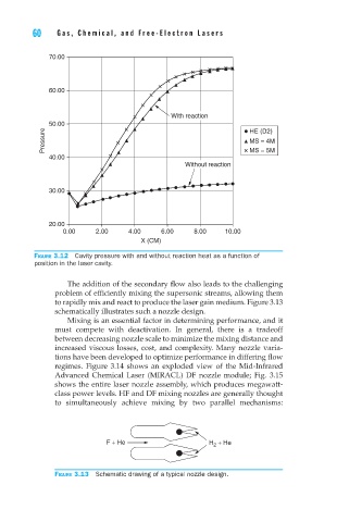
The addition of the secondary flow also leads to the challenging
problem of efficiently mixing the supersonic streams, allowing them
to rapidly mix and react to produce the laser gain medium. Figure 3.13
schematically illustrates such a nozzle design.
Mixing is an essential factor in determining performance, and it
must compete with deactivation. In general, there is a tradeoff
between decreasing nozzle scale to minimize the mixing distance and
increased viscous losses, cost, and complexity. Many nozzle varia-
tions have been developed to optimize performance in differing flow
regimes. Figure 3.14 shows an exploded view of the Mid-Infrared
Advanced Chemical Laser (MIRACL) DF nozzle module; Fig. 3.15
shows the entire laser nozzle assembly, which produces megawatt-
class power levels. HF and DF mixing nozzles are generally thought
to simultaneously achieve mixing by two parallel mechanisms:
F + He H 2 + He
Figure 3.13 Schematic drawing of a typical nozzle design.
61