
Page 270 - High Temperature Solid Oxide Fuel Cells Fundamentals, Design and Applications
P. 270
Electrode Polarisations 247
Figure 9.5 An SEM micrograph showing cross-sectional view of an anode-supported cell. Adjacent to
the electrolyte are anode and cathode electrocatalytic layers of fine microstructure for enhanced
electrocatalysis. Regions next to the electrocatalytic layers have higher porosity and a coarser microstructure
for easier gas transport.
(MOD) is a possible approach to increasing the number of active reaction sites.
An additional macroporous LSM-layer is used as a current coIIecting and gas
distribution layer. The adhesion of the cathode is improved due to the 3-
dimensional penetration structure (Figure 9.6). This approach can lead to a
significant increase in power density, while ensuring long term stability against
thermal cycling by structurally inhibiting delamination. By lowering the
processing temperature (below about 1000°C), it is possible to use a mixed
conducting LSC-thin film (LSC: (La, Sr)Co03) as a cathode, without the danger of
forming unwanted secondary phases. Such cathodes showed an even higher
performance (Figure 9.7), with negligible degradation over an operating period
ofmore than 1000 h and at a current density of 0.4 A/cm2 in air [35].
\/
reaction
sites YsZ intn riim carnoae-layer
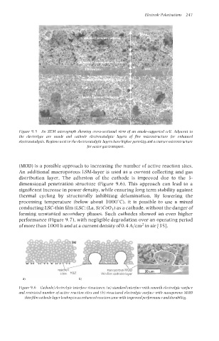
Figure 9.6 CathodelelectrolHte interface structures: (a) standard interface with smooth electrolyte surface
and restricted number of active reaction sites and (b) structured electrolyte surface with nanoporous MOD
thinfilm cathode layer leading to an enhanced reaction zone with improvedperformance anddurability.