
Page 275 - High Temperature Solid Oxide Fuel Cells Fundamentals, Design and Applications
P. 275
2 52 High l't~mpcraturc Solid Oxide Fuel Cells: Fundamentals, Design and Applications
various physical processes, and positions on the arcs provide information on
non-ohmic terms.
The DC method is usually based on a combination of two types ofmeasurements;
ohmic contribution by current interruption, and the measurement of electrode
overpotentials using reference electrodes. The placement of reference electrodes on
solid-state electrochemical devices such as SOFCs presents substantial difficulties,
since, unlike liquid-phase electrochemistry, they cannot be readily inserted into
the electrolyte. In principle, a detailed analysis of the mixed boundary value
problem for complicated specimen geometries and boundary conditions is
required. These difficulties become even more serious when dealing with
electrode (anode or cathode)-supported cells with thin electrolyte film [43-451.
On one hand, such cells are preferred as they exhibit considerably higher power
densities: on the other hand, extracting accurate information on separate
electrode polarisations becomes difficult. Detailed discussion on measurement
techniques and difficulties associated with the use of reference electrodes is given
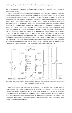
in Chapter 10. For electrolyte-supported cells, measurements are often done with
reference electrodes suitably placed on both the cathodic and the anodic sides.
The electrical equivalent of this arrangement is shown in Figure 9.9.
..............
ZW,,,
working
cathode
%m = i" :I
f ocv cosot
bad 4
1
electronic load :bel cell element'
...........................................
I____
Figure 9.9 Equivalent electrical circuit description of impedance measurement arrangement for planarfuel
cell elements with reference electrodes.
Here, the single cell element is modeled by a number of voltage sources
representing the half-cell potentials. It is to be emphasised that the electrical
equivalent shown in Figure 9.9 is only approximate, and errors in accurate
determination of overpotentials cannot be entirely eliminated. The only way an
accurate estimate of overpotential can be obtained is by solving the appropriate
transport equations for the appropriate boundary conditions - coupled with
experimental measurements.